Need help wiring the "Clearpath killer" for Clough42 ELS - iSV57T-180

Yeah - I definitely wired something incorrectly. I powered up the boost board on its own and the 3.3v light was not on. A quick test of the voltage regulator shows that it blew as part of the process. Good thing those things are cheap and readily available - a 10 pack is on its way for ~$8. I did test the TI board by making a small change to the config.h file and reflashing the board - no errors.

I keep reminding myself that the journey is a big percentage of the fun....
 
OK - I got the new LED&Key board and the one I received this time was clearly made better than the last two - even though I got them from the same source. Odd. I also replaced the voltage regulator successfully. I have everything in the enclosure and it powers up fine to the Clough boot screen but I am getting nothing from my encoder as RPM on the display. Consequently, the servo does not spin of course. I tested the encoder with an ohmmeter (black/blue, blue/white) and they read the same so I am pretty sure the encoder is OK. I flipped the switches back and forth a few times to make sure they were set correctly on the TI board.

I also tried both of the encoder connections EQEP 1 and 2 (and reflashed the code accordingly) same result. I do not have an oscilloscope to do more detailed tests on the board, but in reading a closed post here on github from another user it may be the TI board (again). Are there any good tests that can be done without a scope? If there is a bad resistor can I just get one and solder it onto the board rather than buying a whole new board?

Also, on a side note, I used a laser thermometer to look at the temps on the boost board just to see what was going on there. The only thing that stood out to me were resistors R7 and R8 which seemed warmer than the rest heating up to ~125F pretty quickly. Not sure if this means anything but it is a data point.

Thanks

Tom
 
You sure you have the dipswitch set correctly? I see where you said you flipped them back and forth, so I assume they are.
 
Last edited:
Thanks and I just went out and rechecked them, flipping them back and forth a few times in the process. Both of the S3 switches are toward the encoder connector and the S4 switch is toward the other end of the board, just as it is in the wiki on github. I have sounded out all of the connections so my continuity is good. I read on a github thread that a resistor on the TI board can go bad but the only way to test is with an oscilloscope which I do not have. I am three TI boards into this project (ugh) and I am not relishing a fourth. If I knew which resistor perhaps I could just solder a new one in there....
 
It's either the board or the wiring for the encoder. You flashed it with "release" version? When it's powered up, you should see the Clough42, version number, then .005 feed rate and 0 on RPM. That would indicate board should be ready for signal from encoder. Do the buttons work? You should be able to click the PWR button and it would turn off the servo (if you have an enable line) and only RPM would be displayed. That would indicate the processor is running.
 
It is the most recent - V1.4 and that is exactly what I see on the display. The buttons work, so I agree - it is either the board or the encoder at this point. I am going to put 12V to the encoder and measure the output in the morning. Oddly, I hope it is the encoder....
 
It is the most recent - V1.4 and that is exactly what I see on the display. The buttons work, so I agree - it is either the board or the encoder at this point. I am going to put 12V to the encoder and measure the output in the morning. Oddly, I hope it is the encoder....
The encoder runs with 5 volts. You should be able to see pulses with the voltmeter between the A or B outputs to ground if you turn the encoder slowly. What is the model number of the encoder?
 
Good point - duh on my part! It is the OMRON E6B2-CWZ6C 1024P/R. This morning I measured the voltage between the A outputs to ground as I rotated the encoder slowly. Voltages varied from about 0.27 to 0.97 V as it turned, so it is producing some sort of output.

One thing that was odd was as I was measuring the voltages I glanced over to the display and saw that it had reverted to saying just "CLOUGH42" and stayed there. I have no idea why that happened but it leads me back to the TI board as my issue. I guess I am going to need the fourth board...
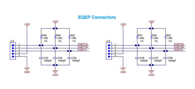
Voltage should swing from low (near ground) to high (above 3.3 volts). I haven't looked at the TI board schematic but there should be pull up resistors on the A & B encoder inputs as the encoder has a NPN open collector output.
 
Yes - Here is the schematic. I think R51, R52, and R53 are not working right (I am on EQEP2) but they show the approximate correct value with a multimeter. Those resistors are TINY - I don't see me being able to replace them. It is odd that the device reverts to "CLOUGH42" on the display after about 90 seconds and is then unresponsive.

I am going to step back, wipe all the code I have tinkered with, download a fresh set from Github and reflash the device. Perhaps I screwed something up in the code....
 

Attachments

  • TI Board.JPG
    TI Board.JPG
    58.6 KB · Views: 101
Back
Top