Needing more than a spark test?

Agreed! A track-hold is a fast and simpler method of grabbing the count for the peak value, and of course, by setting some thresholds, you can get the count of how many pulses had that value, for the histogram - which is what the display is.

You can use a fast A/D conversion, with many samples, to get what amounts to an oscilloscope display of the pulse and afterglow waveform of the scintillation. From that, get the peak value. Lots of computing.

I had thought that unless the shape and duration of the scintillation has informational value in helping determine the energy, I didn't see it as useful. BUT - I am reading, reading, reading. I feel like I am back in study days for exams. There is too much here that I know I just don't (yet) know.

GIven that I do not have any Windows computers at all, I have installed PyMCA, and I will probably roll my own electronics.

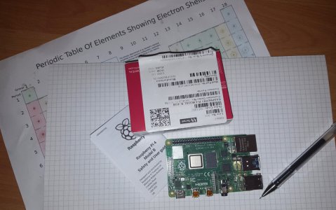
If I can make the outboard stuff USB/Bluetooth, then any platform can use it if the communication format is kept the same. I am very tempted to use a Raspberry Pi with a add-on hat board to work the scintillation hardware, and even that might allow any sensor type. It has the advantage that it comes with it's own little computer, but can just as easily be a USB/WiFi/BlueTooth link to a desktop PC or laptop, and OS agnostic so it can deliver to Windows computers OK.
 
Last edited:
When we read ..
Scintillation Crystal NaI(Tl) NaJ(Tl) 18x30 mm Radiation Detector Scintillator
What exactly is Na(J)?
I have been searching for it, but nothing found yet.
 
As an indication of (one of) the primary issues regarding the use of home-brew XRF to analyze steel alloys, see pages 11-14 and 50 here.

Doing everything you can to minimize the FWHM of the system is vitally necessary in order to distinguish the different components. Using S/W to filter out pulses that will widen the FWHM is probably a requirement, not a nicety. If you're going that far then finding the peak in a digital data stream is almost free; and if your data is 16 bit resolution it would be difficult to improve on that with an analog design. Part of minimizing the FWHM likely includes the "right" scintillator -- some have a steeper photon/Kev slope than others.

As an aside, the processor on a Teensy 4.0 board runs at 600MHz, includes DMA and DSP functions and is 32 bits. It costs $20, and the Arduino-hosted IDE supports a number of audio processing functions . The same company sells a 16 bit ADC kit for $2.65 (!), or you can buy a pre-assembled (and fancier) version for $13.75 (source: pjrc.com. I have no financial or personal relationship with the company).
 
I like the Teensy-4, the size, the price.
I like the Pi-4 more. Cortex-A72 (ARM v8) 64-bit 1.5GHz, auto clock between 600MHz and 1.5GHz depending on load.
I hunted around prjc.com, but not managed to find the ADC yet.

I agree 16 bits is to aim for. If we allow the LSB bit is lost because of threshold uncertainty, we have 2E-15, as the smallest level increment. I don't know the dynamic range expected from the scintillations, but I did see in the post #199 video the option to give the Y-Axis a logarithmic scaling. 146dB is enough to have headroom, even if quite a lot of the lower levels are into the noise floor.

If a multi-channel ADC is used, we have the option of pipelined processing.

The rest of the Pi-4 capabilities are these. It may be overkill, but I am a bit biased because I already have one.

I do like the 4GB SDRAM. Its enough to stack the samples. The rest that comes with it includes graphics to drive 2 screens, and high speed USB3.
--------------------
  • Broadcom BCM2711, Quad core Cortex-A72 (ARM v8) 64-bit SoC @ 1.5GHz
  • 1GB, 2GB or 4GB LPDDR4-3200 SDRAM (depending on model)
  • 2.4 GHz and 5.0 GHz IEEE 802.11ac wireless, Bluetooth 5.0, BLE
  • Gigabit Ethernet
  • 2 USB 3.0 ports; 2 USB 2.0 ports.
  • Raspberry Pi standard 40 pin GPIO header (fully backwards compatible with previous boards)
  • 2 × micro-HDMI ports (up to 4kp60 supported)
  • 2-lane MIPI DSI display port
  • 2-lane MIPI CSI camera port
  • 4-pole stereo audio and composite video port
  • H.265 (4kp60 decode), H264 (1080p60 decode, 1080p30 encode)
  • OpenGL ES 3.0 graphics
  • Micro-SD card slot for loading operating system and data storage
  • 5V DC via USB-C connector (minimum 3A*)
  • 5V DC via GPIO header (minimum 3A*)
  • Power over Ethernet (PoE) enabled (requires separate PoE HAT)
  • Operating temperature: 0 – 50 degrees C ambient
* A good quality 2.5A power supply can be used if downstream USB peripherals consume less than 500mA in total.

One question is how fast are the scintillations going to be arriving at?
Also how long is the pulse and it's afterglow?
Then, how many samples to capture of the event (to be able to sort the valid ones)?

Would a $14 ADC 2-channel device sampling at 1MS/sec be enough? (500kS/sec each)
A 3MS/sec version is about $16.
A 5MS/sec type is $23.

I would normally be looking for 40MS/sec or more, but this is not an SDR, and we want to keep the price down.
The trouble is, any little piece that I think is ideal already costs way more than I want.

Of course - I am trawling evaluation boards, and ready-made add-ons.
 
As an aside, the processor on a Teensy 4.0 board runs at 600MHz, includes DMA and DSP functions and is 32 bits. It costs $20, and the Arduino-hosted IDE supports a number of audio processing functions . The same company sells a 16 bit ADC kit for $2.65 (!), or you can buy a pre-assembled (and fancier) version for $13.75 (source: pjrc.com. I have no financial or personal relationship with the company).
I tried looking through pjrc.com, but I did not spot a 16-bit ADC kit for $2.65.
Since you are easily my XRF reference guru, I would ask what capabilities the A/D converter should have that you consider "enough"?

The scintillation event has a peak, and a duration of afterglow, with two components that have time constants in the microseconds. The afterglow can be bounced by an ill-timed new scintillation, possibly from a different element, and can be higher - or lower. The peak is of interest, and can be captured by a track-hold analogue circuit. The whole event can be delivered as a "slower" event by using a low-pass filter, in effect smearing it in time.

I would expect that one needs at least 4, and ideally many more samples to catch something happening over a microsecond or two. The cost of a 16-bit converter gets above $20 rapidly if sample rates above 2Ms/sec are asked for. Analog Devices (now including Linear Technology) have 14-bit A/D devices that can work 5Ms/sec to 40Ms/sec, at prices that might be contemplated.

The most critical first function components in this are (1) the scintillator crystal, (2) the PMT or Si avalanche Photodiode, and (3) the A/D converter signal capture. That pretty much eats up most of the first $100.

In looking through the A/D converters, I am using the mouser.com site as the first pricing supply reference, and I seek, where they exist, evaluation boards and kits. I discovered that mouser supply very nearly all the kits from Analog Devices that happen to be for devices with LTC part numbers from Linear Technology.

I can keep going, and I can even try prototyping with one or two, but I am interested in what you think on the quality and speed of A/D conversion. There are some 14-bit devices that go fast, and are more affordable. I am still thinking 16 bits, and squealing at the cost. We lose the LSB anyway, but 16 bits can give more than 90dB dynamic range. It will see what looks like "noise", but quite a lot of that can be filtered away (digitally) to discover the peaks of any other elements in there.

While it could be fun to explore XRF materials analysis with this stuff, I would like it if we can find some ready-made evaluation boards and the like hung together such that many HM members who really would like to check out what is in the bit of steel they salvaged, can get one together. I can, and have, designed PCBs with A/D on, but they were for 125MHz sampling RF receiver post down-converter back-ends. In some ways, this mission is the more difficult, and if we can, we want it to be with off-the-shelf PCBs.

Let me know your thoughts on what the A/D performance needs to be.

This thread has become a kind of intense design process exchange between only 3 or 4 members, getting to be an esoteric mix of atomic quantum physics, electronic design, and data processing computing. Are we doing it right? Have we alienated the rest of HM?
 
"Have we alienated the rest of HM? " I think the answer is YES, until you have a working prototype. Then you get project of the month!
Robert
 
Yay! It's Rob. We got something from somebody! :)

Most of the kit needed to even begin "messing with bits on the bench" has not arrived yet, except for a couple of gas lamp mantles, and I have some Americium here on the desk. Oh yes - I forgot the little computer arrived today from Farnell Element14.

I did have the Am241 in the same packet as the thorium loaded mantles, but it dawned on me that putting two radioactive goodies together might have them shooting stuff into each other, and breeding who-knows-what, so the mantles have been banished to the other end of the room.

@homebrewed is definitely the expert here. I think his forum name is apt for his outlook. There will be "prototypes" , and some lash-ups that would be better described as "experiments". All fun stuff will be posted. We are feeling our way here. Until I get some of this stuff figured out, I don't really know what I am doing!
 

Attachments

  • Pi-4 for XRF.jpg
    Pi-4 for XRF.jpg
    319.6 KB · Views: 2
I will be following closely but I may not have much to comment on. The microprocessor and software design are foreign to me. Hey, I can melt lead for shielding if we get that far!
Robert
 
The A/D converter basically determines the vertical horizontal resolution . A 14 bit A/D gives over 16K different states. I don't believe you need even that much resolution.

And yes, I'm still following but you guys are dealing in areas where I haven't got much to offer.

edit: corrected error in 1st line.
 
It is not as good as you might think.
14 bits would give 16384 separate little levels, if one knew the state of the least significant bit.
You don't know the threshold down there where a signal at 1/16384th of the max tips a 0 into a 1.
Effectively, you are down to 13 bits with some certainty.

The data sheets of 14-bit devices cite +/- 0.5LSB as the DNL (Digital Noise Level)
They claim SNR (Signal to Noise Ratio) 74dB (typ)
They claim SFDR (Spurious Free Dynamic Range) 90dB (typ) - a useless spec if it is down in the noise.

16-bit devices can truly get into 90dB range, That should be enough.

The plot display on a XRF alloys display has logarithmic Y-Axis spanning orders of magnitude from the most very feeble scintillation, to max brightness. To have the best chance of extracting the wanted spikes from the noise, I go for the highest resolution I can contrive, with as many samples as possible.

I think I will be after your expertise with material properties to figure out the shapes of the hardware, the shielding. I don't think you can turn lead in a lathe, and I know mu-metal has to be fabricated carefully, and bent slowly, or it loses it's magnetic shielding properties. Using a SiPM diode does not require magnetic shielding, nor a high voltage, but I have no idea about the nature of the probe in general.

A main constraint is that it cannot be "point and shoot". It has to get close enough to take radiation from the Am241.
It has to exclude light really well. Putting a metal sample into a dark box with the probe mounted does work, but I am thinking having something that can be put up against the steel, and seal off the light might be more convenient, and it can use a dark box on a small sample anyway.

Any ideas anyone can dream up at this stage, are welcome.
 
Back
Top