Needing more than a spark test?

Scintillators and PMTs aren't used in commercial EDX tools these days. Instead, they use large-area silicon detectors, basically high voltage diodes. As in the case of a scintillator/PMT, the pulse height is proportional to the x-ray photon energy. That, by the way, is what "EDX" stands for -- energy dispersive x-ray spectroscopy. There is another approach that uses a crystal as a kind of diffraction grating, where the grating is the crystal lattice itself. As the crystal is rotated the incident x-rays are diffracted at different angles toward a fixed detector. Very much like a visible-light monochromator. This type of system offers much higher resolution but, because it acquires one wavelength at a time, it is much slower. Also, you STILL need some kind of detector. This type of system is called a WDX, or wavelength-dispersive x-ray spectrometer. Our old WDX used an ionization detector, a lot like a Geiger tube -- but IIRC the active gas was either a mixture of methane or carbon monoxide (!).

Also check these links out: http://www.noah.org/science/x-ray/detector/ https://benkrasnow.blogspot.com/2012/11/large-area-detector-for-x-rays.html ; and you might be able to acquire some of the hardware here. I haven't gone so far as to check prices from the latter so it still could be out of the range of what hobbyists would be willing to pay.
Addressing whether or not to use large area silicon photodiode sensors. The best of these have similar gain to PMT electron tube, but inherently have the noise floor all solid state semiconductors have. Revese biased avalanche diodes operating at or beyond breakdown along with current limiting, quenching and damping circuitry, have been around for a some time, wheras the large area diode types devoted to X-Ray and other detection are newer speciality products.

I am used to going after the ultimate low noise floor short of cryogenics using pHEMT (PseudoMorphic High Electron Mobility Transistors) in microwave satellite kit. Getting the signal captured with a good signal-to-noise ratio is key. To this add the front-end noise of the gain system. The signal is amplified, and from then on, it is safe, because the noise is amplified as well. The signal-to-noise ratio becomes locked in, because any subsequent processing has to be grossly noisy before that noise can compete with the racket already amplified.

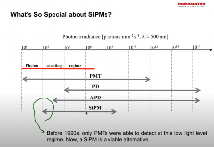
What drives my first choice is taken from a Hamamatsu webinar [1], promoting SiPM (Silicon Photomultiplier) is this chart.
Hamamatsu PMT & SiPM compare.png

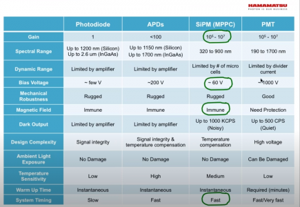
And a table

Hamamatsu PMT & SiPM compare2.png

Notice the region 1 to 10000 covered well by the electron tubes. The noise limit for SiPM diodes is actually around 2000. In the table, the Hamamatsu propaganda stressed only the highlighted stuff in column 3. I put value on the dark output. I would not set the need for temperature compensation against high voltage.

Temperature compensation is a pain, and since the highest voltage I have ever dealt with in really high energy kit was 35kV, or in discharge kit, about 160kV, I don't think high voltage is such a disadvantage, especially since this kind is so high impedance, you can touch it, and it collapses. The last reason is much more prosaic. The tubes seem affordable, and at the level I would play, simple, and were used in an existing, albeit dated, design.

The system considered here is not the WDX wavelength dispersive method, which would be the conventional way of splitting wavelength components into spectrum - like a prism. This is the "other" sort, but the name escapes me. Would it be "Energy Transient Integral Dispersion" or something like that. Even so, I would live to know if the photons scattered from the metal could be deflected into a sensor array by some scintillator.

A basic question to ask is.. are the wavelengths coming back at the sensor X-Ray wavelengths? I have not yet checked the energies for the alloy metals yet. There is just too much to read in a short time. I am still at the somewhat skeptical stage, just thinking through the first recipe. For this to be something we attempt, it had better not cost more than about $200 + some fun project build time.

You did, after all, provide the first DIY link. That leads on to a lot of stuff, mostly in Italian!
If we can cook up something that almost any HM member can replicate, that does only one thing well, with minimum cost, that would be something to aim for. Right now, I am still all too aware of how much I don't know!

[1] Hamamatsu Silicon Photomultipliers Webinar
 
Last edited:
Depending on how much of a DIY approach you want to take with this, it appears it might be possible to make your own proportional gas ionization detector. Ambient-pressure detectors typically use an argon-methane or argon-CO2 blend. They need an electric field around 100,000 volts/cm to bias them into their proportional-detector region of operation, typically achieved by using a metal tube with a thin wire down the middle. The electric field intensity is inversely related to the diameter of the electrode, so thinner wires are better, so don't freak out just yet! By running them at reduced pressure, the ideal gas is isobutane, also known as R600A refrigerant (welly-well now! :grin:). This also drops the voltage necessary to bias the detector into its proportional-detector mode.
Someone who repairs automotive AC systems would have a lot of the necessary equipment/materials to make one of these, although, of course, some machining and electronics skills would be highly desirable as well. The vacuum pump would need to be a 2-stage version that can get down into the 50 millitorr range so the tube could be back-filled with pure isobutane.

One thing that is not often mentioned is that the choice of metal for the outer tube/electrode is important. Making it out of thick, high-atomic-weight metal like steel is bad, because it absorbs x-rays. The ideal material is thin-walled berillium, but thin-walled aluminum might suffice. Obviously, if going with a reduced-pressure detector the tube will have to withstand the pressure differential. Tradeoffs abound, eh?
 
Regarding your question about the fluorescence wavelength(s), the choice of scintillator give you the answer: CsI is used to detect X-rays....so a visible-light spectrometer won't work.

When gas detectors are operated in their proportional mode they are operating in an avalanche-multiplication mode so they do have gain, similar to solid state APD's. Their electronics have a challenging set of requirements because they have to be fast enough to accurately capture the pulse, but quiet enough to get a decent signal out of them. Your experience with HEMT circuits could be an asset here. As you say, the first gain stage is the crucial one in this regard. I've played around with some of the HBT-based DC-GHz amplifiers from mini-circuits, they are inexpensive and not too difficult to work with. You probably would have to go with a resistive output load rather than an inductor, in order to get the flat frequency response you'd need.
 
....... The vacuum pump would need to be a 2-stage version that can get down into the 50 millitorr range so the tube could be back-filled with pure isobutane.
A way of eliminating the need for a high vacuum to obtain a pure fill is to evacuate the tube and fill the evacuated tube with the fill gas and then pumping it down again. This process will reduce the amount of residual air by the dilution factor Pfinal/Pinitial to the same effect as pumping to a much lower pressure. This process can be repeated to obtain whatever degree of purity is required.
 
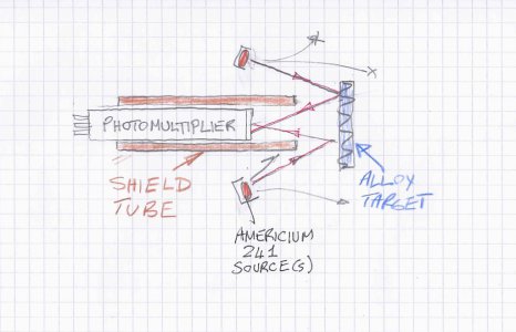
A question (for the DIY design) : What should the tube around the PMT sensor be made of?
Implied in the sketch is that the photomultiplier tube has a CsI scintillator attached to it's front window.

Material Tester Sketch1.jpeg

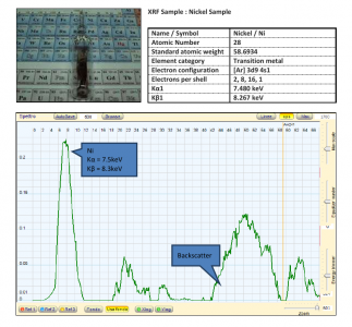
The question arises because I am unsure. Often, electron tubes need metal shields, sometimes of mu-metal to block out magnetic fields. Plastic would block alpha particles, but we are interested only in the florescence emissions from the steel, provoked by the other radiation. The typical result data is like this example for nickel..

XRF for Nickel.png

Notice the backscatter stuff on the right. We would want to minimize the unwanted stuff, by using collimation, and having any surface other than the target and the sensor the radiation might hit, stop it dead, absorb it, make it disappear and die.

Do we need two tubes, one inside the other?
Is lead, or aluminum, or polythene a good choice?
 
Regarding your question about the fluorescence wavelength(s), the choice of scintillator give you the answer: CsI is used to detect X-rays....so a visible-light spectrometer won't work.
OK - so when the radiation hits the metal(s), the energy photons that come back from the K and L electron states returning, with the help of Planck's Constant, are at X-Ray wavelengths, which is why CsI scintillator is needed to yield light that a photo-detector can see. Have I got that right?
 
  • Like
Reactions: rwm
A question (for the DIY design) : What should the tube around the PMT sensor be made of?
Implied in the sketch is that the photomultiplier tube has a CsI scintillator attached to it's front window.

View attachment 320679

The question arises because I am unsure. Often, electron tubes need metal shields, sometimes of mu-metal to block out magnetic fields. Plastic would block alpha particles, but we are interested only in the florescence emissions from the steel, provoked by the other radiation. The typical result data is like this example for nickel..

View attachment 320682

Notice the backscatter stuff on the right. We would want to minimize the unwanted stuff, by using collimation, and having any surface other than the target and the sensor the radiation might hit, stop it dead, absorb it, make it disappear and die.

Do we need two tubes, one inside the other?
Is lead, or aluminum, or polythene a good choice?
I would use lead to stop the x-rays from the source. I would also mount the buttons on a lead disk at the front of the shield tube. I would expect some backscatter from the surface of the target.
 
  • Like
Reactions: rwm
Is a thin glass wall transparent enough?
Alumina?

I am imagining a glass test tube shape, thin only on the hemispherical end. The electrode coming in from the "bung end glued on with epoxy, along with the evacuation tube.

It is possible to use bicycle pump dragged sharply in reverse to make pressures low enough for those toy arc discharge globes to work. It may be possible to fill up the tube entirely with the lighter fluid/car air conditioning stuff, then simply pump down until most of it is extracted, and the remainder low pressure vaporized.

Getting the signal off it requires the discharge pulse current to go through a resistor, as low value as possible (noise), and across it, voltage limiting circuit, and amplifier (low noise). Similar circuits were once used to get the signal off the front electrode of Vidicon, Chalnicon and other types TV camera tubes (from previous century - and millennium).

So we still start with a ring of smoke detector innards, and we put a homebrew (forgive!) gadget up the middle, with some cheap electronics to make high voltage, + low noise amplifier from Mini-Circuits, and offer it up the mic input jack of a cheap credit-card sized computer, + a display app?

Alternatively, the signal goes to a small PIC microcontroller circuit that does the A/D conversion, and sends a serial stream of numbers to a smartphone or PC app via a USB cable?

Am I imagining this wrong?
 
"Robert: No, I don't think so. What the detector can do depends on the scintillation material. "
You seem to be correct. In medical imaging, apparently it is just the CT and fluoro imaging that has gone to flat panel solid state receptors. Looks like Gamma cameras are still Anger design with PMTs.
This is a great thread!
Robert
 
Back
Top