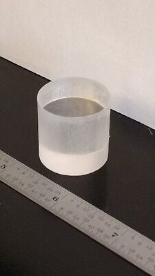
Needing more than a spark test?

Thanks! I do understand x-ray fluorescence as excited by a gamma source. I was wondering how the detector crystal and the PMT would work to separate out the characteristic xrays of each material. The detector crystal is monochromatic (right?) so I assume the higher energies make more photons available to the PMT? I also don't understand how to account for temporal spacing (or lack of) for emission events.
Robert
 
OK - so when the radiation hits the metal(s), the energy photons that come back from the K and L electron states returning, with the help of Planck's Constant, are at X-Ray wavelengths, which is why CsI scintillator is needed to yield light that a photo-detector can see. Have I got that right?
Yep, you got it. Sounds like an indirect way to do things, but it's surprisingly common. A similar approach is used to detect electrons scattered from a surface being imaged by a scanning electron microscope (of course in that case the electrons strike a phosphor, much like the kind you'd find in the old CRT displays). One advantage is that the combination is very robust, as long as the PMT is protected from stray light. That's easy to do inside the SEM vacuum chamber.
 
I see there still some confusion on how a scintillator can produce an X-Ray spectrum. Both RJ and I have mentioned it in previous postings to this thread, but just to repeat..... in essence, the detector system outputs a pulse whose total energy is proportional to the energy of an x-ray photon that hits the scintillator. For a given detector system that generates the same-width pulses per photon, this boils down to pulse height. Higher = shorter X-Ray wavelength, thank you Mr. Planck. You could use the primary gamma ray photons from your Americium to calibrate the system.

In order for this to work right, the incoming X-Ray flux must be low enough so individual photons can be detected. And of course the acquisition system must be fast enough to capture the peak, and sophisticated enough to reset quickly so it is ready for the next photon to come in.

You can buy relatively cheap vacuum pumps for A/C work -- both Amazon and ebay offer many (probably most come from the same Chinese factory). Or you could wait for a 25% coupon from Harbor Freight and buy their 2-stage pump. Getting the instrumentation needed to properly measure the gas pressure when you backfill with your detector gas might cost more than the pump, though.
 
The source beam has to be more energetic than the resultant photons in order to have an interaction. A visible beam will not yield any useful information. The 59.7 Kev photons interact on a nuclear level to generate lower energy photons. These will be in the 5 -50 Kev area of the spectrum for the materials in question. These photons impinging on a scintillation crystal will release a shower of low energy visible light photons with the sum of their energies equal to the energy of the x-ray photon. The energy of a visible photon is in the ev region. E = hf , hence hundreds or thousands of visible light photons foe each x-ray photon.

I expect that there could be two simultaneous x-ray photons but it would be rare. If you recall ever listening to the audio output from a Geiger counter, you can hear the distinct events. The process in XRF is one of sorting each event according to its energy and summing up the events over time to build the spectrum.

Normally, it isn't possible to excite electrons in a target to emit photons of higher energy than the source photons.
 
If DIYing your own gas-based detector (which does not require a scintillator), a sub-problem is getting the right operating pressure. Off-the-shelf pressure sensors that are suitable for this can run you about $600 for the controller and sensor (Kurt Lesker model KJLC-205 + KJLS6000SS). However, if you're willing to roll your own controller circuit as shown here you can get by with just the sensor for about $55 + electronics (2020 price). The circuit uses a single 741 op-amp (!!) so how tricky can it be?

An alternative would be to buy a MEMS based pressure sensor chip like the MS5540C from TE Connectivity, which DigiKey currently has for $22.99. Its low pressure range isn't as good as the thermocouple sensor, bottoming out at 10mbar; and it would require some sort of vacuum-tight electrical pass-thru. For a bit more money I'd go for the thermocouple gauge, which already has a gas fitting on it. I've used them at work and they are very rugged. Throw in an Arduino for the ADC and conversion to pressure and wallah, as an old friend has been known to say.
 
Thanks for reviewing that. That makes a lot more sense now. I was thinking about a much higher xray flux. The Geiger counter example is very illustrative.
So if you use an Americium source, a stock PMT with a scintillation crystal in front of it, it seems like the rest is just electronics and processing? I say "just" although I see that could get real complex.
Following with interest.
Robert


$50
 
Last edited:
Thanks for reviewing that. That makes a lot more sense now. I was thinking about a much higher xray flux. The Geiger counter example is very illustrative.
So if you use an Americium source, a stock PMT with a scintillation crystal in front of it, it seems like the rest is just electronics and processing?
Following with interest.
Robert
That would be a pretty hot source. I would definitely want some shielding between it and me.

re: the rest of the stuff, I think it can be. As I envision it, there would be a gate on the output of the pmt which would pass the voltage through a gate to hold for sampling . The voltage would be presented to a comparitor circuit and computer controlled variable voltage would sweep from zero to some maximum value. When the swept voltage matched to sample voltage a count would be added to the appropriate accumulator. The number of accumulators will determine the resolution of the spectrum. more for higher resolution and longer processing time. The spectrum could be scanned it real time, watching it grow or sample acquisition could be performed for a set time and the spectrum scanned afterwards.
 
  • Like
Reactions: rwm
Thanks for reviewing that. That makes a lot more sense now. I was thinking about a much higher xray flux. The Geiger counter example is very illustrative.
So if you use an Americium source, a stock PMT with a scintillation crystal in front of it, it seems like the rest is just electronics and processing? I say "just" although I see that could get real complex.
Following with interest.
Robert


$50
I saw that one, but I think you can get a photomultiplier tube with a CsI scintillator material already bonded to the front window. Also, other scintillators like NaI(Tl) Thallium-doped Sodium Iodide, though I don't know which suits the aim better. To couple the scintillator to the photomultiplier, you need a drop of lens-coupling immersion oil. That stuff is non-drying so I suppose it would be enough to tape the ensemble together, or use some glue perhaps. Epoxy around the rim might be OK. I am not sure I would shock the edge of a PMT window with hot melt glue.
 
  • Like
Reactions: rwm
I am still trawling everything there is about material identification, learning about Raman handheld spectrometers, finding out about Compton scattering, and what is an Auger electron, and why that produces a special little piece of spectrum.
Part of my graduate study in chemistry was doing Auger and ESCA analysis of catalyst surfaces. I'll offer a general summary of the techniques here.

Both techniques depend on a very precise way to measure electron energies. The analyzer was a tubular structure ~6" in diameter and ~18" long. It consisted of two very precise hollow cylindrical "lenses," which curved the path of scattered electrons. Only one energy would survive the circuitous trip. I don't recall exactly, but I think it had a Channeltron electron multiplier for a detector. An electron gun for the Auger analysis was located coaxially and centered inside the front of the analyzer.

Auger analysis starts with bombarding the sample with an electron beam. These electrons knock electrons from various inner shell orbitals in the sample. This process involves a random exchange of energy, so the scattered electrons are ignored. But after a core electron has been ejected, other electrons, from higher orbitals, "fall down" to replace it. Because orbital energies are precise, and depend entirely on the atom in question, the energies of the transitions are also precise. Additional (Auger) electrons, carrying this excess (kinetic) energy, are sometimes ejected in this process. These electrons "carry" the precise packets of energies as velocities (elecron mss being constant). By analyzing the velocities of ejected Auger electrons (ie, by adjusting the potentials of the electron lenses in the analyzer), you can identify the types and concentrations of atoms in the sample. Each particular element will have a set of well defined Auger electron energies. Back in the day (1970s), we would manually compare a plot of the electron energy spectrum with a table of energies to do the analysis. Nowadays, all the info is in a computer, making elemental and proportional analysis a lot easier. https://en.wikipedia.org/wiki/Auger_effect

ESCA analysis uses x-rays to bombard the sample. But here, the originally ejected electrons' energies are well defined. Photon energy minus orbital energy equals ejected electron energy. The advantage of ESCA is that the electron energies would shift very slightly due to the oxidation state (charge) of the atom, and this could be measured. ESCA is short for "Electron Spectroscopy for Chemical Analysis). The disadvantage was that the number of electrons was a lot less than Auger, so yu had to crank up the electron multiplier and accept a higher level of noise. By and large, ESCA is not that useful for metallurgical analysis. More useful to chemists.

By the way, EDX/WDX are the opposite of ESCA. In an electron microscope, the electrons in the electron beam used for imaging collide with and eject (scatter) electrons from the sample. These ejected electrons are used to form the image. As with Auger and ESCA, the ejected electron leaves behind a "hole" in the orbital structure and outer electrons falling inward do so with precise energies. Some Auger electrons are formed. But most of the transitions dump the energy in the form of photons (x-rays) of precise energies. It's these x-rays that are analyzed for energy levels.

I've made use of Channeltron electron multipliers in other graduate work. And as I understand it, the electron multiplier plate in night vision devices is basically an array of Channeltron-type devices. The way they work - very small diameter curved channels are coated internally with what amounts to a continuous thin film resistor. High voltage is placed across the ends and there is a continuous potential difference along the length of the channel. An electron entering the channel in a straight line intersects the wall somewhere - attracted by the potential - and knocks off several secondary electrons. These are accelerated inward by the potential field, again in a straight line. So they hit somewhere further along the curved wall, eject more electrons, etc. etc. Advantages - No need for a voltage divider, as in a regular PMT. Disadvantage - The thin film resistor can only handle a limited amount of current before it's burned out. So you have to be careful about "how much you feed it." I seem to recall that image intensifiers have some pretty sophisticated circuitry to prevent burnout from bright lights.

Now a specific question for graham-xrf: Looking at post #31, I did not see this type of electron multiplier listed in the table. Was I simply missing the nomenclature? Or was it not included????? And could you use either a night vision image intensifier (which I think you said you had on hand) or a Channeltron instead of a PMT?
 
Last edited:
I suppose this idea deserves at least a lash-up experiment. I have two Americium sources, and I can expect to posses another six soon. I will get hold of a PMT tube + scintillator, either as separates, or as a unit.

I am assuming the PMT tubes used for night vision goggles are unsuitable because they don't let you collect the electron output to an amplifier, instead expending the energy onto a green (zinc sulphide) screen. The other has a fibre-optic bundle intended to couple to aCCD chip. A pity, because that one could see down to 1/12 starlight, and the image of a person in a field would be as speckles of arriving photons, becoming more high resolution as the light level increased.

It would help if I get a little walk-through.
I tried to check out NIST Atomic Spectra Database
I went for "Lines", and typed in "Fe" and pressed return. After about 10 seconds pause, we get the first page of 29609 lines, and I can hear the PC fan revving up as all 4 cores go from 44C to around 60C.

On the way, I see "Levels" and more, and my eye is drawn to "ASD Interface for Laser Induced Breakdown Spectroscopy" (LIBS), but we leave that for now.

I try "Na", hoping to see something of the two bright yellow lines at 589nm and 589.6nm. They are there, but you search a long way down through 7383 lines. I am guessing the numbers are about every possible energy transition between every energy "shell" and all its electron quantum spin states, and only a few would be provoked from a shot of Americium-origin energy.

So start with the energy from one of the smoke detector best shots..

1) It hits the iron, and electrons energy states get yanked about, and settle down, giving back the energy as a photon of a new discrete quantized amount, or amounts, depending on how many electrons got jangled, and by how far.
Let us gloss over what happened to the remainder that did not make the cut (among quanta).
Perhaps we get back a whole bunch of quantized energies.

2) So find out one of these, and divide by Planck's Constant, and also the speed of light, to get at the wavelength.
This wavelength is the characteristic of the iron - it's fingerprint. Also, the amount of energy in it is also such a fingerprint, locked together by the constant-ness of Planck's Constant.

3) This exit photon (might even be X-Ray) hits the scintillator material.
Let us gloss over what happens there, other than to say that the scintillator responds with a feeble flash of (visible light, or not?), but it's own photons anyway. The flash intensity is proportional to the Fe spectrum photon, so we still have a grip on it being iron.

4) These iron-sized photons have to make it through the (thin) glass window of the PMT, and hit a new material, which exhibits the photoelectric effect. Let us here not explore wave-particle duality, nor stay with the photons. It's OK to say we end up with electrons, because that is what photoelectric material does.
These electrons are hopefully proportional to the arrived photon, though possibly only a few because of low efficiency.

5) The PMT multiplier multiplies - by several hundred thousand to a million, but still proportional.
We end up with a pulse of current - the size still related to the fact it came from a smoke-detector -abused iron atom. There are more, thousands of them, all the same strength that labels them as iron.

6) In between, there are thousands more, but they are of different strengths. They would be the nickel, or cobaly, or magnesium sized flashes, They arrive at various times, sometimes right on top of the iron flashes, or each other, but in general, they have drop-out delays characteristic of their electron energy states.

7) In the end, if you display the strength of the pulses that arrive, and display them positioned on a X-Axis such that the higher the energy, the smaller the value, related by Plancks Constant, and the speed of light, you get a signature spectrum for the material. On this last point, I took it from @homebrewed post#15 that this is how the height of the pulse, and the wavelength are related, and so therefore may be displayed.

Posts have happened while I have been writing - apologies if I missed something . Having struck out on the NIST site, I have resorted to Kaye & Laby 14th edition, which I know RJ has likely cussed at at some stage of his life. I just wanted to figure the wavelengths of what the scintillator was supposed to be responding to.

Remembering that we want cheap + cheerful here. We only need to be able to see enough of the elements content, and rough proportions to be able to zero in on the steel. Come to that - the app can do that for us.
 
Back
Top