Needing more than a spark test?

[about Wilkinson ADC]
It is the "pulse stretching" that masks the energy we are trying to represent. It's no problem if all we want to get is the count of arrivals, but the slowed down, low-pass filtered pulse loses much of the amplitude information that allows discrimination into allocating that energy into "bucket accumulator" counts. The necessary thing is to get the area under the roughly triangular pulse waveform, or some good approximation thereof, because Charge x Time integration = Energy

The Wilkinson scheme integrates charge during the pulse rise, so it does get half the area under the pulse; the fall time
is independent of the radiation received, depends instead on clearing stored charge out of the detector.
That trailing edge may not best serve the measurement purpose.

As for pulse overlap, delay-line difference circuit was useful in cancelling out the
slow exponential decay characteristic. It sounds elaborate, but just recognizes that exponential decay
is self-similar, the nanoseconds-ago value times one-plus-epsilon, subtracted from the 'now' value,
equals zero, i.e. no evidence of the old peak in the difference signal. That kinda clobbers the
trailing edge for the measurement, of course. We did it that way for accurate measurements anyhow.

Every two-meter Ethernet wire can give circa 32 nanoseconds of delay.
 
My copy of LTspice seems quirky. The help file didn't install correctly. I have the index and table of contents, but if I click or double click, the page is blank.

If I set the resistor to 1Meg the simulation goes into simulate every ps mode. But 1.0001Meg doesn't do that, nor 999.9k, they simulate in a second. Got some bizarre saturation effects, but they went away when I changed the voltage divider ratio. I have my bias for the LTC6269 at about 1.65V. Seems to work ok.
OK - describing it as "quirky" seems fair. It has some quirks that I wish I could change, particularly the inability to navigate back up a directory tree when using "File -> Open". I rely on the quite long list of previously accessed files.

Between us, we can wring this thing out. I don't want to make another oscillator, and it need not have happened! In my recent previous life, dealing with a FET that still has 13dB gain at 12GHz, the gain at low frequencies (like 10MHz and down) is just so spectacular that you have to be real careful with layout, etc. Here, our transimpedance amplifier is going to take off at the least provocation. Using a guard ring, shielding from 50/60Hz magnetic and electrical influences, etc will all be standard. Beyond that, capacitance at the input, Diode bias, and a whole host of other factors have to be sort of right, or the attempts to build will get frustrating.

The venerable Bob Pease has things to say about these --> LINK Bob Pease Article re: Transimpedance
The book he refers to is attached (it's now freely available).

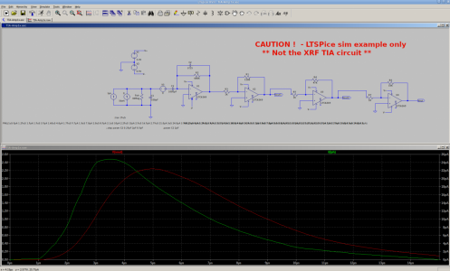
As a gross check, just to see how low we can go with currents, I found one can leave the LTSpice defaults alone, and still get it to work, (but not with everything I try).

TIA-LTSpice-Test.png

This time, I include the LTSPice .asc file, except it is renamed with extension .txt , so that HM will let it upload.
Rename it to TIA-Amp1x.asc, and have a play.
Mouse over Iph, the photodiode generator, for the piece-wise defined current.
Get the probe on Vout2. See it needs more!
Want an osciillator, then start putting MegaOhms by R2.
Without the last two opamps, explore the effect of C2. I commented out the .STEP parameter.

Have a play. You can find out where I messed it up, and let me know. :)
Beyond this, I am much interested in the delay-line pulse processing trick from @whitmore .
I am also looking at fast, accurate peak detectors. This is because if we can use these real fast analog tricks, we dodge a whole lot of computer needs.
 

Attachments

  • vdoc.pub_photodiode-amplifiers-op-amp-solutions.pdf
    2.8 MB · Views: 1
  • TIA-Amp1x.txt
    4.8 KB · Views: 2
Last edited:
@graham-xrf 259 pages of reading! Yet another rabbit hole to get lost in! Thanks for the reference.

Got the schematic to run. Frankly, I think an exponential pulse is perfectly suitable, as compared to the PWL one. For one, an exponential pulse is a whole lot easier to edit! Are you spreading out the gain to ask less of the parts? Or is this a noise issue?

If I step the capacitance, it works as expected. The lower the capacitance, the higher the peak from the first stage and the closer it is to the original. There's excess gain in this chain, so I can rail the output depending on the value of R2. If I step param R2 form 1000k 4000k 500k, Vout1 is fine. No oscillation seen. If one prevents interstage railing, everything is fine. The negative supply is on the hairy edge, should be a bit more negative for headroom.

Don't know what is concerning you, exactly. Perhaps I'm totally missing the point. This wouldn't surprise me one bit!

Asking in excess of 40 dB of gain for U2 is a bit much, but, it seems to work, at least in simulation land. The PWL current pulse is only 25pA high, is this this what you are expecting? What do you expect for the dynamic range of pulses? (Excluding cosmic rays!) Your earlier posted circuit with two LTC6269 amplifiers ran over about 40 dB range in current pulse amplitudes. This new circuit will have worse dynamic range since there's so much gain! I suspect that there will be a DC offset issue with all the gain, due to leakage or bias currents.

Experienced very different behavior in my active filter between simulation and reality on DC offset. My physical circuit was railed due to DC offset and high DC gain. Had to hunt down and hand tweak the positive terminal resistors to get it back to center. The simulation did not show this effect at all. Indeed a simulation of actual values showed it wouldn't work, but it did work in practice. So I had to keep two books, one for as simulated, and another marked up schematic, as built. Simulators and models aren't perfect. They get us close, most of the time, but then bench work is required.
 

Attachments

  • TIA-Amp1x.pdf
    88.7 KB · Views: 0
  • TIA-Amp1x WH.txt
    4.8 KB · Views: 0
More tricky stuff as I tease out what this stuff takes to get the amplifier right.

The (very) small quantities we have to deal with..
I am not used to femto-Amps, and femto-Farads, and figuring what happens when as few as 1% of 379, or as many as 2% of 25,238 electrons suddenly arrive on a reversed biased PIN diode. I want to figure out where the practical noise limitation is, to decide the gain stages. The number of electrons mentioned correspond to the lowest energy one might try for, from Magnesium 1.25360keV, and from the lead shielding Pb 84.936keV, assuming one had some Thorium along with the Am241 to get a gamma high enough to provoke lead.

We can get "higher" counts from lower energy stuff - like Copper. It's 8.04778keV delivers 2438 electrons, at the part of the X-100-7 photodiode sensitivity where we get near 100% of them.

The 59.5keV direct from a smoke detector Am241 provides a valuable calibration point. Each Am241 count delivers 18,0390 electrons. We have to allow the photodiode will only catch about 3% of them - so make that 540 electrons.

[Edit: I had to put in the strike-through modifications. The percentages were about probability - how often a photon is intercepted. When it does, we do get the whole batch of electrons, not a percentage of them! ]

These few electrons kind of "appear", and charge the capacitance of the photodiode. It's as if a capacitor were across a 40MegOhms resistor, and suddenly got some extra charge.
The capacitance could be (say) 60pF from 20V of bias, living with a dark current 3nA.
The capacitance could also be (say) 85pF from 10V of bias, with dark current 2.5nA
Go for lower dark current, capacitance is 150pF from 2V of bias, with dark current at about 1.5nA
Zero bias lets the capacitance go ballistic as the depletion layer gets tiny. Dark current is 600pA, but capacitance is 500pF - so no to that!

This trade-off is why one wants to have a bias voltage that can be varied. I was trying for the simplest possible arrangement of fewest components, already at the optimum value. Thus I want to figure how much noise comes from the dark current, and how much from the thermal. We already know that the noise from the amplifier input is 5.5fA/√Hz. but we want to shunt noise for frequencies lower than 100kHz. A LTC6269 will have a noise racket for 0.1Hz to 10Hz, of +/- 4uV wiggling on it's output. That's no problem if it's in the later stages. but if on the end of the first stage, that's not what we want.
 
Last edited:
More tricky stuff as I tease out what this stuff takes to get the amplifier right.

The (very) small quantities we have to deal with..
I am not used to femto-Amps, and femto-Farads, and figuring what happens when as few as 1% of 379, or as many as 2% of 25,238 electrons suddenly arrive on a reversed biased PIN diode. I want to figure out where the practical noise limitation is, to decide the gain stages. The number of electrons mentioned correspond to the lowest energy one might try for, from Magnesium 1.25360keV, and from the lead shielding Pb 84.936keV, assuming one had some Thorium along with the Am241 to get a gamma high enough to provoke lead.

We can get "higher" counts from lower energy stuff - like Copper. It's 8.04778keV delivers 2438 electrons, at the part of the X-100-7 photodiode sensitivity where we get near 100% of them.

The 59.5keV direct from a smoke detector Am241 provides a valuable calibration point. Each Am241 count delivers 18,0390 electrons. We have to allow the photodiode will only catch about 3% of them - so make that 540 electrons.

These few electrons kind of "appear", and charge the capacitance of the photodiode. It's as if a capacitor were across a 40MegOhms resistor, and suddenly got some extra charge.
The capacitance could be (say) 60pF from 20V of bias, living with a dark current 3nA.
The capacitance could also be (say) 85pF from 10V of bias, with dark current 2.5nA
Go for lower dark current, capacitance is 150pF from 2V of bias, with dark current at about 1.5nA
Zero bias lets the capacitance go ballistic as the depletion layer gets tiny. Dark current is 600pA, but capacitance is 500pF - so no to that!

This trade-off is why one wants to have a bias voltage that can be varied. I was trying for the simplest possible arrangement of fewest components, already at the optimum value. Thus I want to figure how much noise comes from the dark current, and how much from the thermal. We already know that the noise from the amplifier input is 5.5fA/√Hz. but we want to shunt noise for frequencies lower than 100kHz. A LTC6269 will have a noise racket for 0.1Hz to 10Hz, of +/- 4uV wiggling on it's output. That's no problem if it's in the later stages. but if on the end of the first stage, thats not what we want.
If we stick to the simplistic model that you recently posted, I simulated varying Cd from 50pf to 500pf in 50pf steps (20dB) and saw a 2 dB reduction in output pulse amplitude. 860mV @ Cd=50pF, 636mV @ Cd=500pF. That's not a whole heck of a lot. I admittedly don't know much about these kinds of diodes, but, is the dark current that important in this circuit topology with AC coupling?

I changed the DC dark current from 0 to 1nA, change is on the order of < 0.25% in pulse amplitude. Got to read up on noise simulations, been a while since I've done one.
 
Practically speaking, the type of detector we're trying to use here limits the energy range we can "see", regardless of the amplifier chain design. At lower energies the packaging starts to absorb incoming photons, and at higher energies the much-less-than 1mm width of the PIN junction means that very few are absorbed. If 60Kev photons only have a 3% chance of being turned into hole-electron pairs inside the X100 diode, 80+Kev is even worse.

Fortunately, the X100 is most sensitive in the energy range we're mostly interested in.
 
If we stick to the simplistic model that you recently posted, I simulated varying Cd from 50pf to 500pf in 50pf steps (20dB) and saw a 2 dB reduction in output pulse amplitude. 860mV @ Cd=50pF, 636mV @ Cd=500pF. That's not a whole heck of a lot. I admittedly don't know much about these kinds of diodes, but, is the dark current that important in this circuit topology with AC coupling?

I changed the DC dark current from 0 to 1nA, change is on the order of < 0.25% in pulse amplitude. Got to read up on noise simulations, been a while since I've done one.
I did try to make it clear that the circuit I posted was not my TIA circuit, except in an indirect way. It was more about checking out LTSpice simulations. I do not have 4 opamps in a row like that, but what is there is useful as a passing test-bed. Try reducing the value of C3, to 100pF, or 10pF, and see the signal go away. Note that the 0V voltage source V3, my form of handy ammeter, shows a negative current pulse, only because of the way I connected it with the positive towards the op-amp.

For me, I wanted to avoid getting up to all sorts of arrangements to deal with pulses that overshoot below the base line, restoring zero, and getting any input offsets either insignificant, or compensated for, forced the DC isolation capacitor, just like they do with PMTs.

I will post more on my design, and thinking soon. Mark's pulse-stretched amplifier has me intrigued. If he discovers the pulses it makes do have amplitudes be a good analogue of X-Rays from metal samples, then it's a runner because it by-passes a forty bucks ADC.
 
Last edited:
I did try to make it clear that the circuit I posted was not my TIA circuit, except in an indirect way. It was more about checking out LTSpice simulations. I do not have 4 opamps in a row like that, but what is there is useful as a passing test-bed. Try reducing the value of C3, to 100pF, or 10pF, and see the signal go away. Note that the 0V voltage source V3, my form of handy ammeter, shows a negative current pulse, only because of the way I connected it with the positive towards the op-amp.

For me, I wanted to avoid getting up to all sorts of arrangements to deal with pulses that overshoot below the base line, restoring zero, and getting any input offsets either insignificant, or compensated for, forced the DC isolation capacitor, just like they do with PMTs.

I will post more on my design, and thinking soon. Mark's pulse-stretched amplifier has me intrigued. If he discovers the pulses it makes do have amplitudes be a good analogue of X-Rays from metal samples, then it's a runner because it by-passes a forty bucks ADC.
Yes, I understood it wasn't your TIA circuit. What was unclear was the actual point you were making by posting it! Perhaps, that's due to our differing engineering styles, or that of being from one country or another. Cultural style, is a term for it. When one works for a multi-national company, one gets exposed to regional differences in approach to a problem.

Now that you have pointed it out, it's a bit clearer. Using ideal elements can be a helpful technique to isolate an issue.

Yes the whole point is to have some waveform with a characteristic that is proportional to what we would like to know, in our case, the number of signal electrons coming out of the detector. Stretched waveforms can be fine, as long as they continue to be proportional to signal.
 
Looking at it from a theoretical standpoint, the Laplace Transform of A*f(t) = A*F(s). By extension if we use a linear filter we know the output is proportional to the amplitude of the input. That won't be a surprise to anyone who has spent any time at all in the vicinity of this thread.

I don't think it is a stretch to assume that the pulse height coming out of a TIA or charge amplifier being tickled by an x-ray generated event also is proportional to the total energy of the pulse, so I'm pretty confident that the amplitude of a stretched-out version of the pulse will be as well. The pulse height of our low-pass filtered signal won't be anywhere near the height of an unfiltered pulse, but that's something that can easily be addressed with some post-filter amplification.
 
Yes, I understood it wasn't your TIA circuit. What was unclear was the actual point you were making by posting it! Perhaps, that's due to our differing engineering styles, or that of being from one country or another. Cultural style, is a term for it. When one works for a multi-national company, one gets exposed to regional differences in approach to a problem.

Now that you have pointed it out, it's a bit clearer. Using ideal elements can be a helpful technique to isolate an issue.

Yes the whole point is to have some waveform with a characteristic that is proportional to what we would like to know, in our case, the number of signal electrons coming out of the detector. Stretched waveforms can be fine, as long as they continue to be proportional to signal.
Re: The circuit - I needed to reach for one - any one - that we could try in your LTSpice install, to see if it would run, or prang, or do something different to my experience with it. If you got the same result as me, then we would no longer be thinking your LTSpice was broken, or just different. The circuit was just one of many I threw together, just to try out some something at the time, and discarded. I may have been trying to learn how some LTSpice feature was used. Maybe I should have tried a different one, but it was one of the few that actually still ran OK. The rest have been adjusted to death! Sorry if it was misleading.

Re: Using contrived elements.
Yes, I do that all the time. It's quite hard to model the arrival of a photon. Just because we have a bunch of charge that arrives, we do not yet have a "current" looking like the exponential SPICE source, or the piecewise linear make-believe. To get the photon electrons supply to become a current, we need that charge to move in a certain time.

Modeling the arrival of a photon
I was thinking of using a pair of SPICE voltage-controlled switches driven by a pulse waveform, to charge a capacitor to exactly the amount of coulombs represented by some photon. Then, at the time for a pulse, the switch to the charging resistance opens, and the other switch closes, connecting that amount onto the photodiode expected capacitance, and 40M shunt resistance. Basically the whole steady state X100-7 photodiode equivalent circuit, with it's bias and everything.

The switch contrivance that delivers the current transient can hardly help but change the charge on the input DC isolation capacitor, and so move electrons in the opamp transimpedance input.

Not limited by artificial, lossless SPICE switches, we can have more than one artificial photon, of various energies, arriving at different times. For us, one "biggest" photon, plus one "smallest" photon will do. Then that might allow us to play with gain distribution, and even figure out how low we need go in the face of noise currents from other sources. It lets me know exactly how many stages I need, and how to drive the ADC.

I will soon go over my circuit, and the design thinking in it, and why I did what I did.
 
Last edited:
Back
Top