Needing more than a spark test?

Thanks for the warning. Yes, I will back up all the old KiCAD stuff and purge it. Have a bunch of stuff to do in FreeCAD first, before I play with KiCAD again.

Just now drawing up a backplate for my lathe. Couldn't buy one for my lathe, with the right features. I can blame supply shortages on this. Same cause as the chip shortages. So bought some cast iron and going to make one. Need to design the backplate, since the manufacturer didn't post the dimensions. Suppose it is fun, but really would have preferred to have bought the backplate. The raw cast iron disc cost nearly as much as the fully machined piece.
 
Non-reflections..
Related to arranging geometry of arranging the sources around the sensor, we get it that a simple shield between is OK. The photons cannot go around corners. Also, we have to accept that the good stuff is pinging out in all directions, so therefore into shielding around it's side, and to the rear. We only get to play with those headed in the direction of the material being tested.

We want to arrange things that as many as possible gammas can arrive there, sneaked under the photodiode, so that as many as possible of the X-rays that get shaken out have not much way of escape other than by scattering back into the diode. Of course, the X-rays too will start off in all sorts of random directions, going into and through stuff. We can only capture the fraction coming at our sensor.

Here I make an assumption. A gamma coming at the material at an oblique low angle will always go into the material, and shower forth X-rays :)
It will never "reflect", no matter how shiny the surface polish, nor how low the angle. I say that, but we all know how even a grinding block "reflects" if you look at it at a small enough angle. I leave it to others to speculate why this is so.

This is just a little musing of mine, getting to grips with what is "reflection" anyway, and how it happens. When we polish surfaces, we do get things to atomic dimensions. The wavelengths of light, are around 400nm to 700nm. Ultra-violet gets to as short as 10nm, but is mostly around 200-400nm. The longest wavelength in our scheme belongs to magnesium, at 1.2536keV, with a wavelength about 0.989nm.

The gamma from smoke detectors has wavelength around 21pm. It will go right into the middle of any atom, though it might miss stuff, and pass right through. Magnesium has atom size parts 141pm to 173pm, and spacings around 320pm metallic radius (so double it). So, there can be no "reflection", and there is no limitation on range for the lucky X-ray photon that happens to exit heading towards the photodiode.

Get up close!
Thus, quasi-optical geometry is misleading. Basically, we want as large an area of stuff irradiated as can still see a straight line back into the diode, even if this is at an extreme low angle. Short-range back-scatter right under the diode does not have an advantage over X-rays that had a longer journey to get there. Therefore it seems to me that if we do not tip the sources at an angle, but instead point straight ahead, and put the diode + smoke detector sources assembly down as close as possible to the sample surface, consistent with getting X-rays from the furthest sample extent to still see a straight line into the sensor, then we have possibly a better count gathering arrangement.
.Just a thought .. :)
 
Even xrays can be focused, but only under very specific conditions. Google "Wolter telescope". But you are correct that the much shorter xray wavelength places extreme requirements on the mirror surface.

Regarding the subject of flat vs. tilted source geometry, I think you are correct in saying that getting everything as tight as possible, consistent with the need to shield the detector from our sources, is the best approach to take. A ring of flat sources is a simpler geometry, that's for certain -- but I don't think it's the one that will get the total area of the source closest to the sample. This also could be quibbling over an improvement that's buried in the statistical nature of the counts coming in :) The only way to tell is to do it both ways and compare....now, where did I put that other set of sources that I haven't ordered yet :D
 
The only way to tell is to do it both ways and compare....now, where did I put that other set of sources that I haven't ordered yet :D
Duh - you are so right about the sources. We may have got a few together, but for how much longer do we believe smoke detectors will be made with Am241? It's not as if we can just get hold of more gamma sources, even weak ones!
 
My apologies for the hiatus. I have had, and still have, a number of current things that will stall me.
I have been getting quite far into bringing together the bits of design, and getting into KiCAD. So here I discuss a little, and ramble on a little, and I have a question.

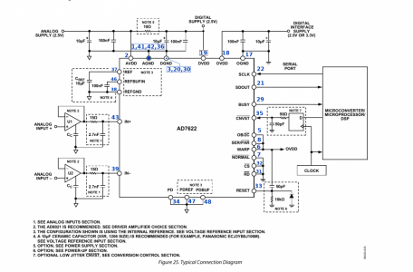
One thing I have discovered is no matter where the source, be it DigiKey, Mouser, Analog.com, even though one is purchasing their product anyway, none can bring themselves to simply provide the pin-outs, footprints, and even simulation models without wrapping it behind the need to run a executable on one's PC to access it. They all have their various names for it. It seems there are good reasons KiCAD do not bundle the DigiKey KiCAD library.

Thus, I have made my own symbol, and linked footprint for the analog-to-digital converter.
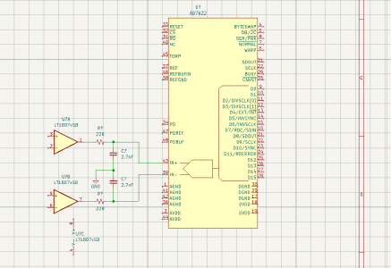
ADC_Symbol KiCAD.png

AC noise reject filter
The gain of the transimpedance amplifier is enormous, no matter what configuration, and it is actually quite difficult to eliminate the hum from magnetically and voltage field induced interference. I suppose in many places, things are electrically quiet enough for it not to be a problem, but in my design, I push the limits right to the noise floor. The ambition is try for the lowest energies between 1.2keV and 2keV. The absorption probabilities are between 1% and 10%. Magnesium and aluminium are just about possible, and getting the proportions of silicon in the iron might also happen.

I intend to add in my version of the Twin-T AC 50Hz -60Hz filter at a place where I might exploit the presence of a buffer-driver pair that has to be there anyway. At worst, the filter gets it's own dual op-amp, costing about $4. Do not take fright at the look of it. Several components are in parallel, and a pair can be replaced by one part. Some shown are not connected anyway.
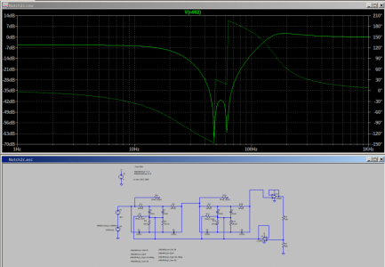
Twin-AC-Notch Filter.png

If the opinion is that something like this should be an included feature, then we get to why I designed it to do 50Hz as well as 60Hz. I thought it may as well be universal. As seen in the plot, one notch takes out 50Hz, and the other hits the 60Hz.

Bit Banging the Raspberry Pi
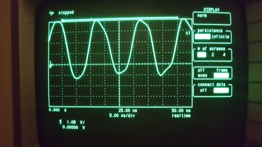
It was a little experiment. We decided to throw out various Pi libraries. I will spare the detail, and just say we ran a little C program which when compiled, was only about 8K, devoted to wiggling a pin as if sending data. We tried it up to about 66 MHz, and clearly could have gone much further, but it had reached the loop speed of the little C program. I don't understand where the program execution boundary is, but the program was trying for 100MHz, and can be persuaded to do it. We could have modified the program max out on the GPIO pins, etc, but there seemed little point. 2MHz is all we need for ADC clocking, and we can use (say) 20MHz or something for serial data transfer. The traces came out somewhat over-bright exposed on the Samsung Galaxy phone camera, but anyway, you get the idea.
Raspberry Pi GPIO at 66MHz.jpg
Above is 66MHz off a GPIO pin. We never have to go anything like that fast!
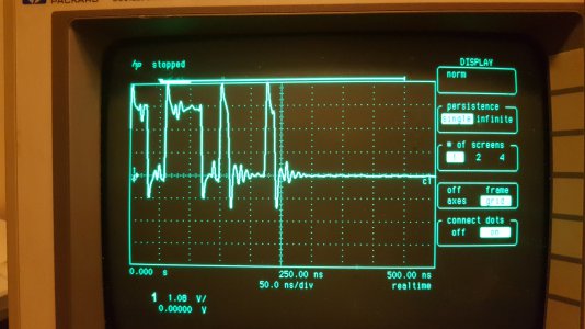
Try for some real data..
Raspberry Pi Data GPIO.jpg

Here I am sending the data hexadecimal CF21 into the un-terminated GPIO pin. I switched on the "connect the dots" display. On this old scope, it does 1GSample/sec if on a single channel mode. With the right resistor, and correct pF capacitor, the overshoots and ringing goes away, and it turns into a prettier square wave. The code in there is 0xCF = 11001111 followed by 0x21 = 00100001. This is still clocking out at 66MHz.

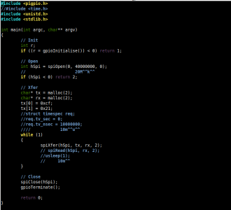
The little C program I used is here ..
Pi-BitBangin C Program.png

I can't really figure out why so many examples I see are a mess of libraries and bloated code.
The advice here is "Don't use the default Python" unless its an undemanding application like zillions you can find on the net. I am not after educational demos here. The Pi does it easily. Comparing to C program as the reference set to 1, a compiled Java program manages about 1.2. Python is at around 75!. Old-style C might be a bit wild-West, and needs careful discipline in making and using space, (like using those "malloc" instructions), but it lets you do nearly anything.

Conversion Rate - and "looking into the past"
I am going to try for the conversion clock to run all the time at 2MHz, driven by the Pi, to provide 20 samples out of the 10nS pulse duration, capturing perhaps 1/2 a second's worth at a time in a cyclic buffer. I decided to save on the components and not build in the hardware comparator to provide the "pulse is here" trigger. The detection of a pulse, and it's recent past, is taken from the cyclic buffer. It's an all-software trigger with a certain amount of false pulse weeding out ability.

Noise- again!
The quality of the conversion, and it's signal-to-noise ratio also depends on the speed, cleanliness, and low jitter of the conversion initiation signal from the Pi. I hope the signal from the Raspberry Pi GPIO can be dressed up nice enough to do this. The test circuit on the Pi is now mostly together. The darn stuff is just a bit small = "I need better soldering kit" ! :)

AD7622 Pi3 pins.png

Stuff that, (I think) needs to be in there.
Several kinds of noise-conditioned power sources. I choose 10V or 12V diode bias, driven by a tiny charge pump like LT1317B (£4.91) or similar, at 600kHz. If not then simply a couple of lithium cells. The size of the pulse is much decided by the capacitance it has to spread itself into, and the benefit of having 75pF at 12V bias instead of 190pF at 2V, or a disastrous 500pF at near zero bias, outweigh the small increase in dark current from 1.5nA to 2.5nA.

We have to not allow the DC component dark current in anyway, which is why I choose AC coupled at the transimpedance amplifier. That would be the only place it happens. The circuit does not have any return-to- baseline overshoots, nor ambiguities.

The 5V supply will ultimately come from a USB. It has to see at least a filter, with common mode and differential surface mount choke inductors, and the usual associated capacitors. In this design, a 2.5V separate low noise LDO regulated supply is needed for the analog part of the ADC converter. That too, gets filtered, with only one place common to the digital zero.

The 3.3V digital supply is stolen from the Raspberry Pi, but also filtered, and digital bit energy ground bounce limited with resistors in the digital signal line, and all the usual sensible precautions.

In the end, there is not much physical stuff on the circuit, and, (when they again become available), I hope to use the tiny Raspberry Pi Zero 2C in there, with only a USB line, or BlueTooth link to the phone or PC for display. The plot is on a live web page in the Raspberry Pi. No software app needed on the phone. Only a browser.

Vary the gain?
I plan to include one of those op-amps that have 3-Bit control of gains, to allow a "zoom-in" option on the low energy regions of the plots. The amplifier can hopefully see down into the 30pA to 100pA range (where the noise is). Most arrival energies should be in the range 100pA to several hundred pA, and some up to around 1.3nA. The Pi can control which gain range is selected. Of course, this gain stage is right at the end of the chain, where the outputs are given to the ADC using a 2.5V reference for the full resolution.

The Question..
Mostly for Mark - given that you have already tried it, just asking what sort of "tick rate" can we expect? I would hope at least some Hertz.

What we have here is that the pulse events may not come by very often, but when they do, it's all over in 15uS. The one quantity that sets the pulse length is the photodiode biased capacitance (75pF in my plan). The pulse has a near exact relationship to the energy in it. The delay distortion in extreme low pass filtering of all other kinds of pulse-stretching blur this relationship. I would love it is we would be getting a high speed buzz, but somehow, I think that might be unlikely.

That's it for now folks. I know this is extreme nerd stuff, especially if encountered by HM members who don't quite get it that this stuff is directly machining-interest related. I will get back when I have the proto together. I am OK to mail (a few) bare PCBs, but I will check in here before I commit to making them.
 
Last edited:
A few comments on Graham's latest post. First, it's good to see some progress, since I've been stymied by a cascade of machining-tool issues. Hopefully they will be resolved soon (part of the problem is my own fault, unfortunately). But because of that I don't have a lot of new data w/regard to count rates. Damitall :)

On the positive side, the rehab work on our rental is done, fini, over. We've passed the headaches on to a property management firm, so there should be much more time available for fun stuff.

Regarding the circular buffer approach, that looks like a great way to implement all sorts of pulse-selection algorithms without needing to worry overmuch about the resulting processing overhead....as long as the buffer is deep enough. But I'm a bit concerned about using the RPi's GPIO to operate the A/D -- Linux (and Windows) have all kinds of interrupts running in the background so the timing could vary all over the map if it's determined by a program running in the foreground. Unless there's a way to configure the particular OS to behave like an RTOS, I'm still leaning toward a microprocessor-based ADC front end where I know that all the interrupt-driven processes are the ones I want to run, and I can kill them when I need to without crashing the system.

Noise inputs -- both systematic and random -- are part of the territory we will need to deal with. High gain circuits are just going to be noise sensitive so robust H/W and S/W approaches will be needed. There's a reason that commercial versions of XRF spectrometers are expensive, the vendors have spent a lot of effort addressing those kinds of things. After my experience with the high levels of noise coming in from that on-board switcher (on the PocketGeiger) I'm strongly leaning toward purely linear supplies: or switchers that are very well isolated from the high gain stuff -- both physically and electrically. As an alternative, how expensive are two series-connected 9V batteries? You can't get much lower noise than that....and if they're just used to bias the detector, they will last just as long as ones just sitting on the shelf.
 
On the positive side, the rehab work on our rental is done, fini, over. We've passed the headaches on to a property management firm, so there should be much more time available for fun stuff.
Yay!. You have been put through the wringer a bit. Glad to hear you are now getting back to normal. I say that carefully, because for you "normal" sometimes looks a bit messy and dangerous!
Regarding the circular buffer approach, that looks like a great way to implement all sorts of pulse-selection algorithms without needing to worry overmuch about the resulting processing overhead....as long as the buffer is deep enough. But I'm a bit concerned about using the RPi's GPIO to operate the A/D -- Linux (and Windows) have all kinds of interrupts running in the background so the timing could vary all over the map if it's determined by a program running in the foreground. Unless there's a way to configure the particular OS to behave like an RTOS, I'm still leaning toward a microprocessor-based ADC front end where I know that all the interrupt-driven processes are the ones I want to run, and I can kill them when I need to without crashing the system.
Forgive that I get a bit expansive here. This is the very point I wanted to test, and establish.

The thing about process allocation in Linux is that one can set it to run user processes with absolutely exclusive grip on the CPU, but that leaves one with the responsibility to "let go" periodically. In practice, hardly anybody ever needs to. The kernel default clever settings maintains enough room in the loop for all the "housekeeping". The vast majority is available to the user, and slow-downs are never hang-ups.

I think Windows has seven levels, only the top one being user space. What goes on in the others is unknown, except we can see it takes CPU time as a law unto itself, and is often doing significant uploads (why?) This is the reason none of the satellite Earth Station servo software I ever became involved with could be entrusted to a Windows OS, quite aside from most client's needs not to rely on any kind of "trust" anyway.

There is some kind of synchronization scheme in the task allocation, so that the intervals one sets in programs, in do in fact loop on the expected microsecond. This is how I noticed that an expected 1uS repeats data stream repeat had exactly that interval on the scope. Then, as we "sped up" things, we got to the point where only 2/3 of the code could execute before the interrupt. The result was an automatic adjustment to the loop to have execution in 15uS instead of 10uS, which is why the display shows 66.666MHz. I have to appreciate that the individual bits in that stream looked like 100MBaud !!

Linux kernel has 2 levels, both of which can have user access. The keyboard poll is default at 300Hz. Some users who like to run high end audio recording applications in real time, and still want "instant keyboard response" will set the rate to 1kHz. Where millisecond latency down to less than 5mS is needed, say when using Jack Audio connection kit with several MIDI interfaces, you use the repository, and invoke the low-latency or real-time kernel. Again, very few users experience enough data drop-out to need this. Those who do would probably run the OS headless. As it happens, during this little test, the whole display, network, keyboard, mouse, BlueTooth, etc. everything was running! If I had a monitor on it, I could have gone browsing, although I dare say running a bloat like Chromium browser playing Ed Sheeran on YT would have slowed it down a bit! Instead, I let it get on the WiFi on the default DHCP address, and I accessed it via SSH from my desk PC.

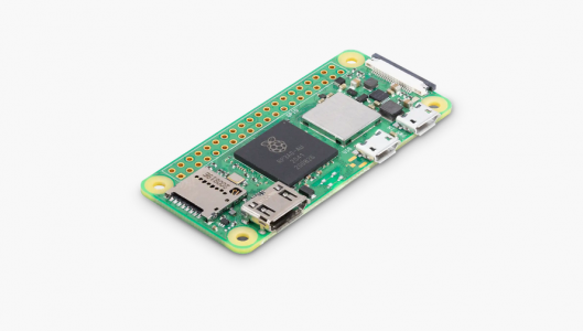
I do get it that we are never going to be thrashing a Pi into oblivion like this. I wanted to see if the (pathetic) little heatsink I used would be enough. Not having a fan involved is an objective. Of course, a full-blown Pi4 is not needed. An older Pi3 Model 2B is enough, and indeed the aim here is to use the (damn fast!) little Raspberry Pi Zero 2W. You can appreciate the size from the picture. I am reasonably sure that a $15 bucks little computer like this is actually up to it. It won't have the overhead of a user screen, and indeed, one can just install the stripped down "headless" version if need be. I imagine all the XRF software to be running in there, with no need for any outside resource other than the user running a browser with interactive buttons on a display page.

Raspberry Pi Zero 2W.png

Re: The Cyclic Sampler.
I worked it out. Suppose on samples 20 in a 10uS period. That's 2MHz.
Suppose we get greedy, and pessimistic, and decide to stash a whole second's worth. So two million samples, each two bytes worth.
The 4Mbyte of memory is not such a big chunk of the half a GigaByte of SDRAM in there! (in a Pi Zero).

OK then. We get it that the "tick rate" might be quite slow, maybe several per second, up to some hundreds per second. The thing is, when the pulse arrives, it's all over in about 10uS or 15uS, and there is then a whole milli-second or two before the next event. I know a whole second's worth might involve sorting out a lot of pulses, so maybe we can choose say half a second, or less. These times are an age for a computer. I am now reasonably sure even a (slow) 2MHz cyclic stash leaves more than enough time to play with it's numbers.
Noise inputs -- both systematic and random -- are part of the territory we will need to deal with. High gain circuits are just going to be noise sensitive so robust H/W and S/W approaches will be needed. There's a reason that commercial versions of XRF spectrometers are expensive, the vendors have spent a lot of effort addressing those kinds of things. After my experience with the high levels of noise coming in from that on-board switcher (on the PocketGeiger) I'm strongly leaning toward purely linear supplies: or switchers that are very well isolated from the high gain stuff -- both physically and electrically. As an alternative, how expensive are two series-connected 9V batteries? You can't get much lower noise than that....and if they're just used to bias the detector, they will last just as long as ones just sitting on the shelf.
There are good charge pump circuits that can deliver switcher type low(ish) noise volts. I do agree that the 2 cells lithium solves quite a lot of the problems, and a saves a whole bunch of components. Of course, the cells have their own price, and on needs to mount them somehow, but I am sure we can find a way. OK then, everything about our layouts and choices are going to be hostile to noise, and we use a pure DC for the bias.

The lithium cells may have a working life somewhat more than I have left for myself! :) The bias current does have some noise, but I am not sure how much. The diode "equivalent" circuit may not represent it right. A reverse biased diode is not a real resistor with resistor molecules bashing about in it. I was after getting the transient pulse away from it, through a capacitor, into the transimpedance amplifier.

I know you are using a modified Pocket-Geiger. There will be more space on my protoype PCB than I can use. There is no extra charge for "step-and-repeats" except if there are a lot of holes to be drilled. One possibility is that if you have a modified pocket-geiger circuit, and want to put your stuff on a PCB, you can post here, or send it to me, to include on the prototype gerbers. I have to check what the deals are now, but I am thinking one might fit several of both our efforts on one PCB proto minimum size, and just share them.

I have two schemes. One uses the LT6269 dual op-amp in a straightforward transimpedance circuit. The other is the version with the front-end JFET, and scheme to lose the noise with frequency component.
Unfortunately, the dual opamp I bought is only available in MS8E, or we know it as MSOP-8. The SO-8 package only does the single op-amp LT6268.

Soldering !
Now becoming a problem for me. I need to resort to the technique normally used for BGA arrays, meaning placing the solder first, and the part, then covering with the flux goo, and holding the iron into the flux blob, and waiting for the melt. Otherwise, it's going to have to be the "heat it all up" way that you have practiced.
 
Last edited:
I hesitate to mention this again, but for prototyping SMD I'd use a hot air gun and solder paste. No iron, no extra flux. A temperature controlled hot air gun can be bought new for less than $35. Comes with different size nozzles and adjustable air flow. I've seen them as cheap as $10. They really are the cats meow. Easy to use. Doesn't move the parts. The $35 one has an auto shut off when the gun is put in the cradle. Turns on again when you pick up the gun again.

Have no ownership or interest in any of these companies, just a happy user.
It's OK. I was thinking of you anyway. :) I now have a real nice hot air gun with LCD display of temperature setting, fan speeds, cool-down blow, etc. It's just that the previous adventure, with previous hot air gun, ended up as a bit of a bust!. Try and imagine surface mount bits getting blown into places where the next time they might move is into a vacuum cleaner. Then imagine second try, scorching things like the paint-stripper it was designed to be. Cheapo crap method of "getting hotter" was by "slow down the air flow"! By then, I was already far past the "give-up" point.

I have been looking at some YT videos where the guy was removing only the micro-SD card holder from a circuit. He pinged the metal casing tabs first, then used a generous splodge of the transparent, slightly yellow-looking flux across all the pins at once. He put the end of the soldering iron into the flux, and in a few seconds, the whole thing un-soldered. The same with replacing a IC with DD case. This was a phone repair. He covers it all with the flux stuff, puts his iron into it, and it all comes away. he even used the trick for soldering the new chip in.

At least some of what I have to be doing is changing the odd part on an already built board. The hot-air trick, is, I think, probably the best when soldering all the components on in one hit. They just "align themselves" onto the pads.
 
:) those little nozzles are great for rework. I had to rework an SD card holder before. Used hot air and flux.

And sorry to hear about your previous misadventures with hot air! Would have soured me a bit as well. Having decent tools always make the job go better.
 
Back
Top