Needing more than a spark test?

1/2 inch is getting right up close, but I think you are right in the approach. I did wonder if one can get "too many" pulses?
We can always cut down on the number of sources used. I'm going with the worst-possible count rate, after seeing what my current setup is doing. This sort of belated discovery is what a test bed is all about so I'm not at all surprised to find some flys in the soup!

Back to your first comment, I immediately created a trouble ticket asking for .scad files to be on the allowed-to-attach list.

We are just going to have to solve whatever it takes to shape some lead. ??

The "focusing ring" doesn't need to be made out of lead. At least, I wasn't planning on it. Turn a ring out of aluminum and glue it to the lead aperture plate. Then glue down the pared-down source disks -- hot glue, silicone, epoxy, whatever. BTW, the source disks don't have be round. Cutting off chords to make a square will accomplish the desired effect, as long as the disk just fits inside it. It should be possible to do this with relatively low risk of releasing Am241 but I still would do it outside while wearing a particle mask.

The hole in the aperture plate I'm currently using wasn't all that difficult to do, but having some experience with "grabby" metals (brass, to be specific), to start the hole I used the largest drill I've got that has been dubbed so it drills brass OK. Basically the two cutting edges on the drill flutes are knocked back with a stone so they have neutral rake. That worked fine, but I did take it pretty slow, too. Then I enlarged the hole using a tapered hand reamer. Hey, some machining-related stuff! Now we're good for another 65 pages of posts :laughing:

The drill modification is called Dubbing, and I did it with a 600-grit diamond stone. Those drills are kept separate so they don't get used for things like steel and aluminum.

I'm thinking that the shield ring can be made out of a sheet of lead the right thickness, by cutting a strip and rolling it into a circle. Additional messing around with my model indicates the shield ring only needs to be .180"/4.6mm high to completely shield the detector from the source gamma rays. It should be at least 1/16"/1.5mm thick, so it really will be a short tube rather than a washer. I wouldn't want to make it much thicker, else it will block some source gammas from the sample. I'd just glue it to the aperture plate, too. Gamma rays striking the bottom of the ring will still encounter the aperture plate so the ring doesn't have to sit perfectly flat on the plate.

Finally (for this post, anyway) I noticed a potential issue with the X100 detector with regard to oscillation. I was fooling around with a small sheet of copper to see if I could get some copper XRF pulses to show up and when I got the sheet very close to the detector the PocketGeiger board started oscillating. The detector is a big antenna sitting near two high-gain amplifiers, so introducing some capacitive coupling between them all got things going. If you're going to be building up your own detector front end, that's something to consider. Or if simply modifying a PocketGeiger like me.
 
Hey, some machining-related stuff! Now we're good for another 65 pages of posts :laughing:
That vtcnc raised a ticket for allowing .scad files means at least he is OK with the thread.
I have another going on the ways of making it of lead, and indeed other materials, including 3D printed fabrication with bits of lead here and there.
I'm thinking that the shield ring can be made out of a sheet of lead the right thickness, by cutting a strip and rolling it into a circle. Additional messing around with my model indicates the shield ring only needs to be .180"/4.6mm high to completely shield the detector from the source gamma rays. It should be at least 1/16"/1.5mm thick, so it really will be a short tube rather than a washer. I wouldn't want to make it much thicker, else it will block some source gammas from the sample. I'd just glue it to the aperture plate, too. Gamma rays striking the bottom of the ring will still encounter the aperture plate so the ring doesn't have to sit perfectly flat on the plate.
Similar to the several schemes I was trawling. It should be perfectly OK to make a groove for a ring of lead sheet. It's the sort of thing that can be shaped by hand with the aid of a Sharpie tube, or a loose drill (blunt end), and pressed into the groove.
Finally (for this post, anyway) I noticed a potential issue with the X100 detector with regard to oscillation. I was fooling around with a small sheet of copper to see if I could get some copper XRF pulses to show up and when I got the sheet very close to the detector the PocketGeiger board started oscillating. The detector is a big antenna sitting near two high-gain amplifiers, so introducing some capacitive coupling between them all got things going. If you're going to be building up your own detector front end, that's something to consider. Or if simply modifying a PocketGeiger like me.
I get that - and I would not expect my amplifier to oscillate. It's gain is distributed anyway, and no fields can get at it. No capacitive couplings.

The first stage has high enough gain to preserve the S/N ratio, yet low enough to guarantee bandwidth, and preserve the pulse information down to the noise floor. The next stage brings the signal up to near the final signal to be sampled, but there is also a differential driver for the ADC capable of adding gain. This one doubles a 50Hz/60Hz notch filter. The robust signal is sent to the ADC with a shielded twisted pair, with separate analog reference. I would like to push the ADC to the limits of it's dynamic range, so that the least significant bits are rattling around reading noise that originated in the first amplifier front-end. That is the hope, anyway. The actual construction may fall short of that, when tried out, but it's where I aim for at the start.

For cost reasons, I have not given it some or the nicer features. Your scheme of software switchable gain range would be nice. Other than that there is a X100-7 diode on it, and one pad set that can take an op-amp, the pocket-geiger does not have much that I like. Given that it is a bit of a pain to de-solder the diode, I consider sawing that part off, and fixing it at right angles to the amplifier board, but I think, in the end, I remove it.
 
@homebrewed :
Mark, I would be very interested in what might happen if you were able to get a 6" red coded thoriated TIG welding rod, and waved it in front of your detector. I realize you may not have TIG welding stuff handy, in which case there will come a point where I can try this myself.

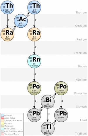
I was looking at the decay chain of thorium, to radium, then back and forth via actinium, then about a minute being radon before rattling around and ending up as lead. I happen to have a bunch of thorium gas mantles (Chinese), and I know a welding rod is 2% thorium.
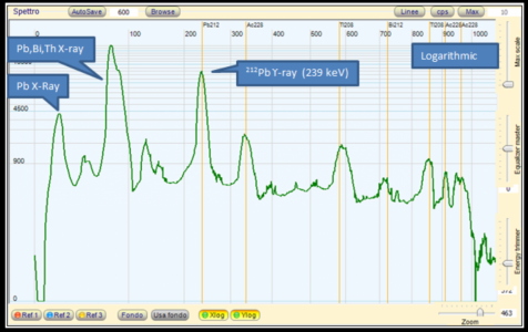
Thorium Decay.png . . . Thorium Mantle Spectrum.png
 
Last edited:
Getting better counts
Not that I want to be distracting too much from the present effort with Am241, but I was thinking about maybe changing, or augmenting the radioactive bombardment in a safe enough way.

Thorium in gas mantles
The stuff has higher energy gammas. I have about 10 of these, purchased around 2019 in a batch for not much, but now, they are not made anymore, and getting rare. There is one eBay seller, selling singles at £6.00 (about $8 bucks) each, only 9 left, and when they are gone, that's it!

I am imagining a "trench of hot-melt" glue, or similar retaining method, the glue holding in thorium oxide. This to give a continuous ring, or two, or a great big wide & thick washer shape worth. It's radioactive area face around the diode, except the geometry does not allow any direct gamma into the diode. The gamma has to expend itself illuminating the test surface.

I imagine cutting a disc shape groove 3 or 4mm deep (say), then coat with release agent, and pack it with thorium mantle stuff. This is then potted with glue, or epoxy. Fit the potted radioactive ring into the lead recess. Alternatively, if one wants the angled focus approach, make a bunch of ex-mantle thorium oxide slugs.

Alternative Thorium from TIG Rods
Screw the gas mantles! One can get a set of 10 TIG welding rods for £9.00 (about $12 bucks), of which 2% is thorium by weight.

I think about simply bending a thoriated TIG welding rod (red painted end identifier). A whole 2% of by weight it is straight up decaying thorium.
Without even (yet) suggesting separating the thorium from the tungsten steel, how about simply bending a short length of 2.4mm diameter TIG rod into a ring, pressed into the angled annulus trench. Why not two, or three?

Use the Am241 as well!
Why not a ring, or two, or three, of 2.4mm diameter rods around the outside of the smoke detector Am241 slugs? Basically stick everything we can find that is radioactive, and easily obtained, into that space?

If the rods can be hammered flatter, one could have a increased exit area. Finally - not that I know how to do it, but I give consideration to the naughty thought of extracting the thorium. You can't heat it loose. It melts at 1755C! but I think only in a vacuum, or argon-inert thing.
I guess one could dissolve it in nitric acid, then do chemistry to drop out either the tungsten, or thorium. @RJSakowski will be telling us not to do this stuff.

What can it do for us?
Reading about the decay of thorium, and all it's daughter products, I see it has a whole mess of gammas coming out of it. They are energetic enough show us Tungsten, Osmium, Platinum, Gold, Mercury, and the lead proportion in free machining steel. We would not be interested in any elements heavier than lead, but the array of gammas coming out of Thorium, starting from less than Am4241 60keV, and going up beyond 900keV, seems to good to ignore.

Treat all the above as a rambling notion. There could be all sorts of holes in such a plan, and I have not done enough reading to be certain of it's viability, but so far, it seems possible.
 
Last edited:
I don't have a thoriated TIG rod but I do have some thoriated tungsten wire that was used to make SEM hairpin emitters. Now if I can just find it.... "dang, I remember seeing that SOMEWHERE around here".....

I'm still refining my aperture plate/focusing ring/shield ring design. Correcting a math error allowed me to move the sources in quite a bit more than my initial design, while minimizing shadowing of the source-to-sample path due to the shield ring. I also experimented with the notion of using a 1/8" thick lead aperture plate with the idea that it might allow me to get rid of the shield ring, but that made the overall geometry worse.

Something I'm wondering about are some differences between my Am241 sources. Some look like the ones Graham has shown, with a peened-on central disk, but the majority look quite different. This can be seen in the first photo of post #642 of this thread. Hopefully they're just a slightly different design (rather than lacking the desired Am241), but if so that impacts the focus ring and shield ring design -- the smaller peened-on disk actually permits an even-closer arrangement of the sources. I suppose I should assume worst-case and design them to accommodate the larger active source area.

This discovery also makes me happy that I decided to go ahead and make an ionization-type radiation detector so I can check my sources.
 
Last edited:
I'm still refining my aperture plate/focusing ring/shield ring design. Correcting a math error allowed me to move the sources in quite a bit more than my initial design, while minimizing shadowing of the source-to-sample path due to the shield ring.
Since gammas can't reflect (because of tiny wavelength), and can't go around corners, the shield ring need only be as high as the top of the diode body, and the radioactives on the other side of the ring need only be such that no gammas can see a straight line to the diode. There needs to be shield underneath the diode, or underneath the whole circuit, to drop out most of the external background noise. There will remain some you cannot stop.
This discovery also makes me happy that I decided to go ahead and make an ionization-type radiation detector so I can check my sources.
For other readers of this thread..
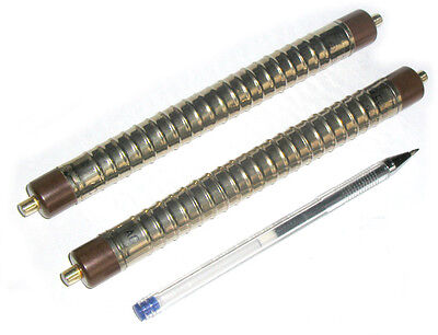
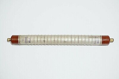
This morning I bought one of these.. --> SBM-19 Geiger Tube for £33.60
It happens to be from Ukraine, from Russian cold war surplus. I know there is supposed to an ironic aspect to this.

There is another from Romania, at similar price when you include the shipping.

The SBM-20 types look the same as SBM-19, and are more plentiful. They are much the same, but a bit less sensitive, although better for use in very high radiation before saturating. A single costs about $20 bucks with free shipping, or two for $38.

Both of these types are robust things that should work for longer than you have life left, unless beaten up by inappropriate circuit discharges. One only needs a tiny discharge current to get a count

[DO NOT get those marked "parts only" for about $11, nor the 10x pieces for $109]

There are a variety of uncased project modules without tubes, some with displays, in the range $45 to about $65
I see complete geiger counter units in little plastic cases and various bells & whistles seem to sell in the $80 to $125 range.

Folk who may, in the end, want to get an XRF analyzer together, do not actually need these things, unless they are interested. You may have your own ideas on how to make a (safe) radioactive racket, and some may be lucky enough to have good stuff in the rocks in their back yard! :)
 
Last edited:
Due to that 14 billion year half life, you should see very little activity from the thorium. In contrast, the AM241 has a half life of 14 years.
 
  • Like
Reactions: rwm
Due to that 14 billion year half life, you should see very little activity from the thorium. In contrast, the AM241 has a half life of 14 years.
I set that against being able to place grams of the stuff there, as against nanograms. On a YT video, I saw a pack of TIG rods placed on a Geiger counter. The background count went up from 80-100 at the start, to over 1000. I do agree that if it has been around so long, it cant be losing atoms often, but by my count, a gram or two has got way more than 14 billion decaying atoms for us to play with..

Let me try..
Avagadro's Number is 6.022140857×10^23 atoms per mole.
There is the problem that the atoms are big fat heavy things, so a mole is 232.038 grams
(Please somebody weigh a TIG welding rod for me)
Going on it being nearly all Tungsten (98%) at 19.3g/cm^3 and 2% thorium at 11.7g/cm^3
A welding rod is 6" x 2.4mm (howzat for mixing units)? Volume is 15.24 x 0.24 =3.6576 cm^3
Weight of a 6" rod = (0.98 x 3.6576 x 19.3) + (0.02 x 3.6576 x 11.7) = 70.036 grams
The welding rod should have (0.02 x 70.0357/232.038) x 6.022140857e+23 = 3.63530844446e+21 Thorium atoms in it

It takes 14.05 billion years to lose half of them.
So 3.63530844446e+21/(2 x 14.05E9) = 129370407276 atoms decay per year.
There are 31536000 seconds in that year.
Dividing 129370407276 / 31536000 yields 4102.30870359
Our TIG welding rod should be losing a paltry
4102 atoms every second.
We would be using about 5" of it, so make that 3418 per second.
Probably only about a quarter of them would be in the direction we find useful, so about 854 per second.

I do agree that that is not much! The photons that come out are very energetic. Just not very often.
Is it worth trying to use Thorium to get a glow out of stuff?
Should we be maxing out on Am241 little things instead?
How many can we fit around the diode?

-----
Once a Thorium has decayed, it becomes Radium, which has half-life 5.7 years.
Radium goes on to Actinium, wasting half of itself in 6.1 hours going back into a lighter version of Thorium.
Lighter Thorium then has another try at becoming Radium (lighter version), but half is lost in 3,6 days.
Becoming Radon, half lasts 55 seconds, and in 140 millisecond, it's radioactive lead.
Not many minutes later, visiting Bismuth212, Polonium212, and Thallium 212, it ends up as lead shielding. :)
 
Last edited:
I set that against being able to place grams of the stuff there, as against nanograms. On a YT video, I saw a pack of TIG rods placed on a Geiger counter. The background count went up from 80-100 at the start, to over 1000. I do agree that if it has been around so long, it cant be losing atoms often, but by my count, a gram or two has got way more than 14 billion decaying atoms for us to play with..

Let me try..
Avagadro's Number is 6.022140857×10^23 atoms per mole.
There is the problem that the atoms are big fat heavy things, so a mole is 232.038 grams
(Please somebody weigh a TIG welding rod for me)
Going on it being nearly all Tungsten (98%) at 19.3g/cm^3 and 2% thorium at 11.7g/cm^3
A welding rod is 6" x 2.4mm (howzat for mixing units)? Volume is 15.24 x 0.24 =3.6576 cm^3
Weight of a rod = (0.98 x 3.6576 x 19.3) + (0.02 x 3.6576 x 11.7) = 70.036 grams
The welding rod should have (0.02 x 70.0357/232.038) x 6.022140857e+23 = 3.63530844446e+21 Thorium atoms in it

It takes 14.05 billion years to lose half of them.
So 3.63530844446e+21/(2 x 14.05E9) = 129370407276 atoms decay per year.
There are 31536000 seconds in that year.
Dividing 129370407276 / 31536000 yields 4102.30870359
Our TIG welding rod should be losing a paltry
4102 atoms every second.
We would be using about 5" of it, so make that 3418 per second.
Probably only about a quarter of them would be in the direction we find useful, so about 854 per second.

I do agree that that is not much! The photons that come out are very energetic. Just not very often.
Is it worth trying to use Thorium to get a glow out of stuff?
Should we be maxing out on Am241 little things instead?
How many can we fit around the diode?

-----
Once a Thorium has decayed, it becomes Radium, which has half-life 5.7 years.
Radium goes on to Actinium, wasting half of itself in 6.1 hours going back into a lighter version of Thorium.
Lighter Thorium then has another try at becoming Radium (lighter version), but half is lost in 3,6 days.
Becoming Radon, half lasts 55 seconds, and in 140 millisecond, it's radioactive lead.
Not many minutes later, visiting Bismuth212, Polonium212, and Thallium 212, it ends up as lead shielding. :)
FYI TIG electrodes are 7" long (177.8mm). Interesting we are counting atoms now!

Does the 4n thorium decay chain emit gammas? The Wikipedia page only shows alpha and beta emission, but don't know if the chart is complete. Edit: It appears that some of the particle emissions are accompanied by gamma radiation, but not shown. Would be nice to see that chart.
 
Last edited:
FYI TIG electrodes are 7" long (177.8mm). Interesting we are counting atoms now!

Does the 4n thorium decay chain emit gammas? The Wikipedia page only shows alpha and beta emission, but don't know if the chart is complete.
It was @RJSakowski mentioning the slow decay that had me have to check it out. There was no place I could easily discover what a welding rod would do. Sure - every time the Geiger ticks, we are counting the demise of an atom!

I was just after making this as easy to get together as possible, and the difficulty of ready access to safe isotopes without spending crazy money, or coming up with a design that won't have it's main ingredient available in the future was a concern.
-----------------
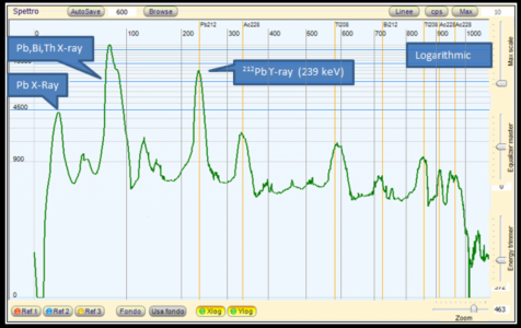
From a Thorium gas mantle

All the Thorium spectra plot I can find are crappy. I reworked the plot in post #653 and tried to make the X-axis lines clearer, and the blue Y-axis grid also. It's easy enough to see the energy log scale along the top.

The first peak is plain old lead (that the Thorium has finally decayed to) being given a XRF glow at (I think) at 10.55 and 12.61 keV

The next big fat peak (I think) might be the 74.97keV and 84.93keV XRF main glow from the lead. This stuff happens to be stronger than the Am241 (59.5keV), so would set off XRF glows from lesser metals. I don't know what is firing this one up. When a Thorium does decide to decay, it loses alphas (heliums 4n), plus however large a photon is needed to represent the missing mass of the end products, compared to what was there before the decay.

The first actual proper labeled atom decay peak is the one at 239keV. This is the from the radioactive lead Pb212 remnant from previous decays.
It is a genuine gamma, half-life 10.6 hours, which is why, I suppose, it has a high count.

The next one looking like at 340keV is labeled Ac228, which would be coming from Actinium on it's way to becoming the lighter isotope of Thorium228. The decay is beta, which would be electrons if they slowed down, but they are going at such a high fraction of the speed of light, they have increased mass, which does stuff to atoms they hit.

The next one just to the left of 600keV is the decay of previously created Thallium, having come from Bismuth that happened from the lead Pb212 in the third peak mentioned earlier. These things have very short half-lives. However it happens, that beta will easily whack into anything it hits, and make the stuff glow X-Rays

The small peak at around to the right of 700keV is the Bismuth212 remnant becoming Polonium212, half of which becomes lead 300 nanoseconds later.

The bigger peak at about 850keV is another photon from Thallium208 becoming stable lead.

The last two highest energy peaks between 900keV and 1MeV are from the original decay from Radium into Actinium
You can tell from the count (Y-axis) that they may have high energy, but don't happen so often.

Thorium Mantle Spectrum2.png
 
Back
Top