New PM-1236T Lathe

Thorough review of the 1236T. Surprised to hear about the economy chuck quality.

I got a 1127VFLB last year and so far enjoying it. I made a barbell bar for a friend recently and used steady/follow rests first time with a few mistakes. Last year I tried to cut some thread and learnt to change gears. No desire to do it again. It was a hassle to put just right gear slack to make the machine quiet. Been wondering about 1236T/1340GT but no way I can keep both. Any idea what would a 1yr old 1127 fetch? Buyer has to come to my place as no way I can ship it.

Also I realize that with variable speed in 1127, the torque at low speeds is not much, can't take heavy cuts. So now I understand why geared speed is better.
09a1069730980559d4c5c4a7c2f9cf90.jpg
 
Yeah, it's the cross slide lock tool. My 1236T had a hex head set screw in place and the tool in the toolbox. I use the cross slide lock all the time so this little tool was a nice discovery.
I was wondering what that was for! I don't think I ever would have figured that out. Unfortunately, that will be blocked by the DRO scale so I won't be able to put it to use.
Also, you can run the wire to the light fixture through an existing grommeted hole in the bottom of the electrical box. Then you can close the door on the electrical box. ;-)
Ill take obvious things that were right in front of my face for $500 Alex.
 
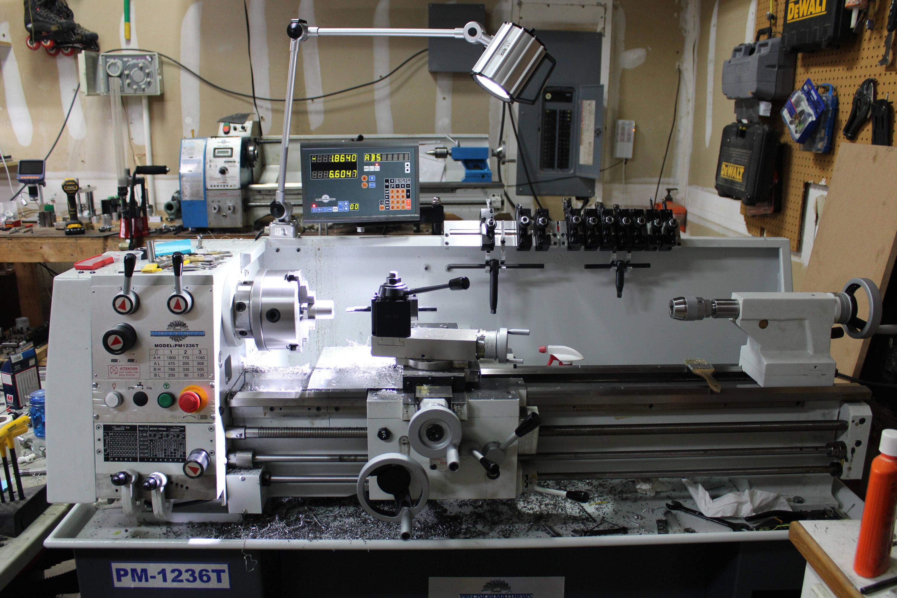
I got the DRO delivered on Monday and I am just about finished installing it. It came with a bunch of mounting hardware, but I couldn't figure out how most of it was supposed to be used. I modeled up part of the machine and the scales and made some new mounts that I think will work better.

The guards they included are pretty nice though. The look like they will be very easy to install and very effective. My only gripes about the DRO kit are that there aren't really any install instructions, so you are more or less buying a kit that you still need to figure out how to make work. A few pictures and recommended install practices would have been nice.

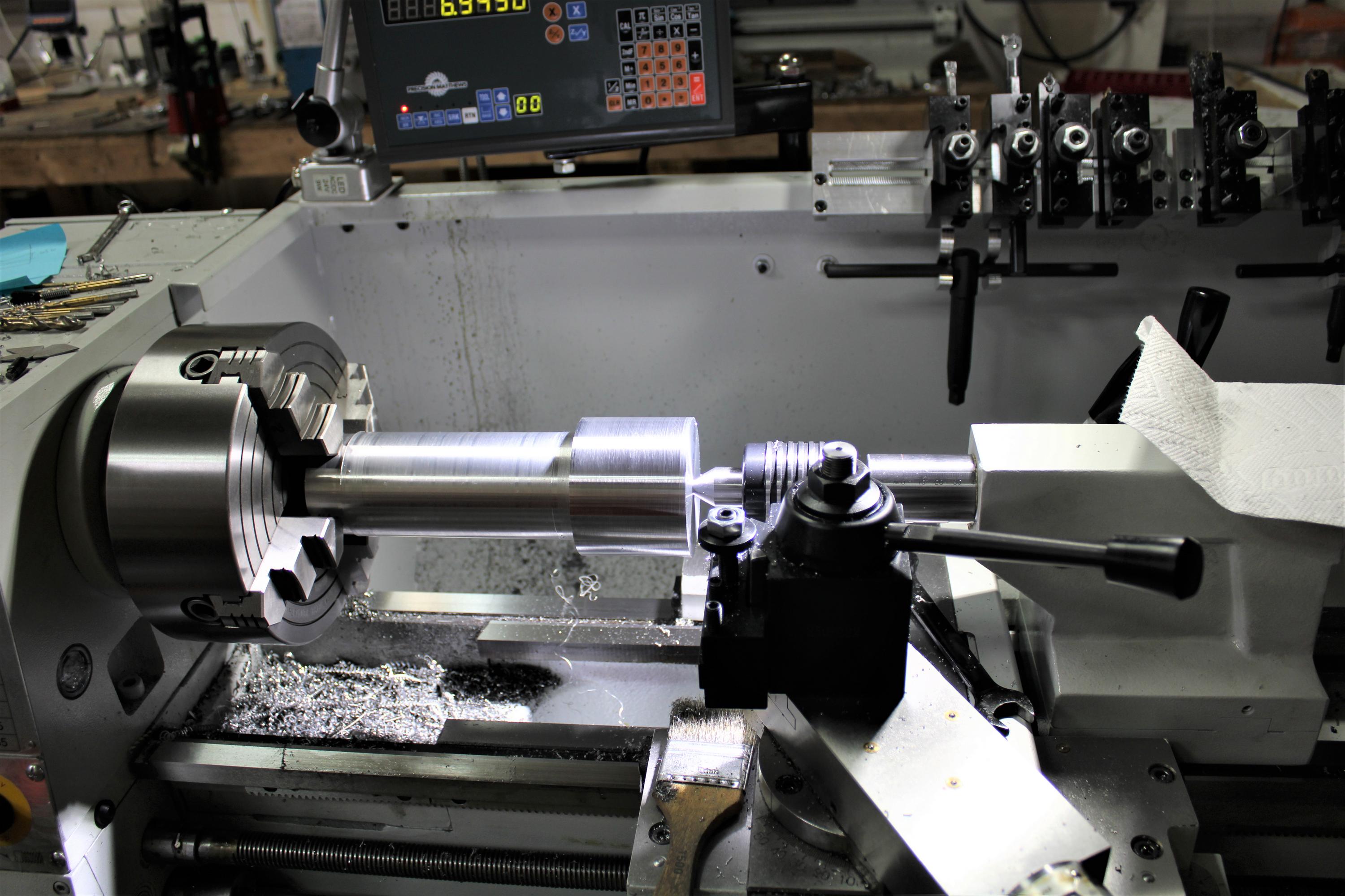
Once I had the model and decided how I wanted everything arranged, the install was fairly straight forward. I am not sure what kind of alignment tolerances are needed, but the Z scale was straight within about .005" and the X is around .001. Its tough to tell if there is any twist or anything, but I think they are close enough.

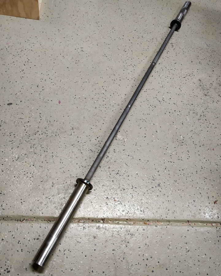
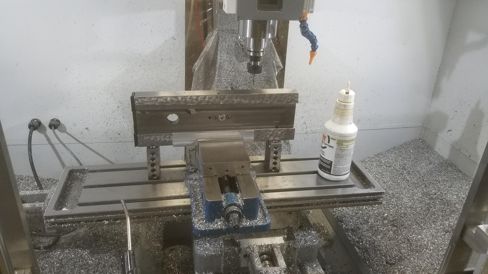
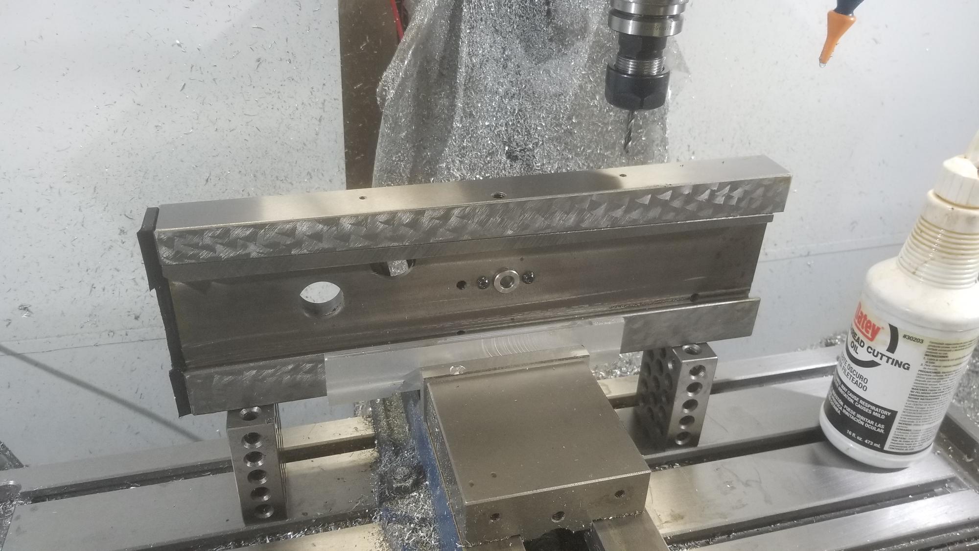
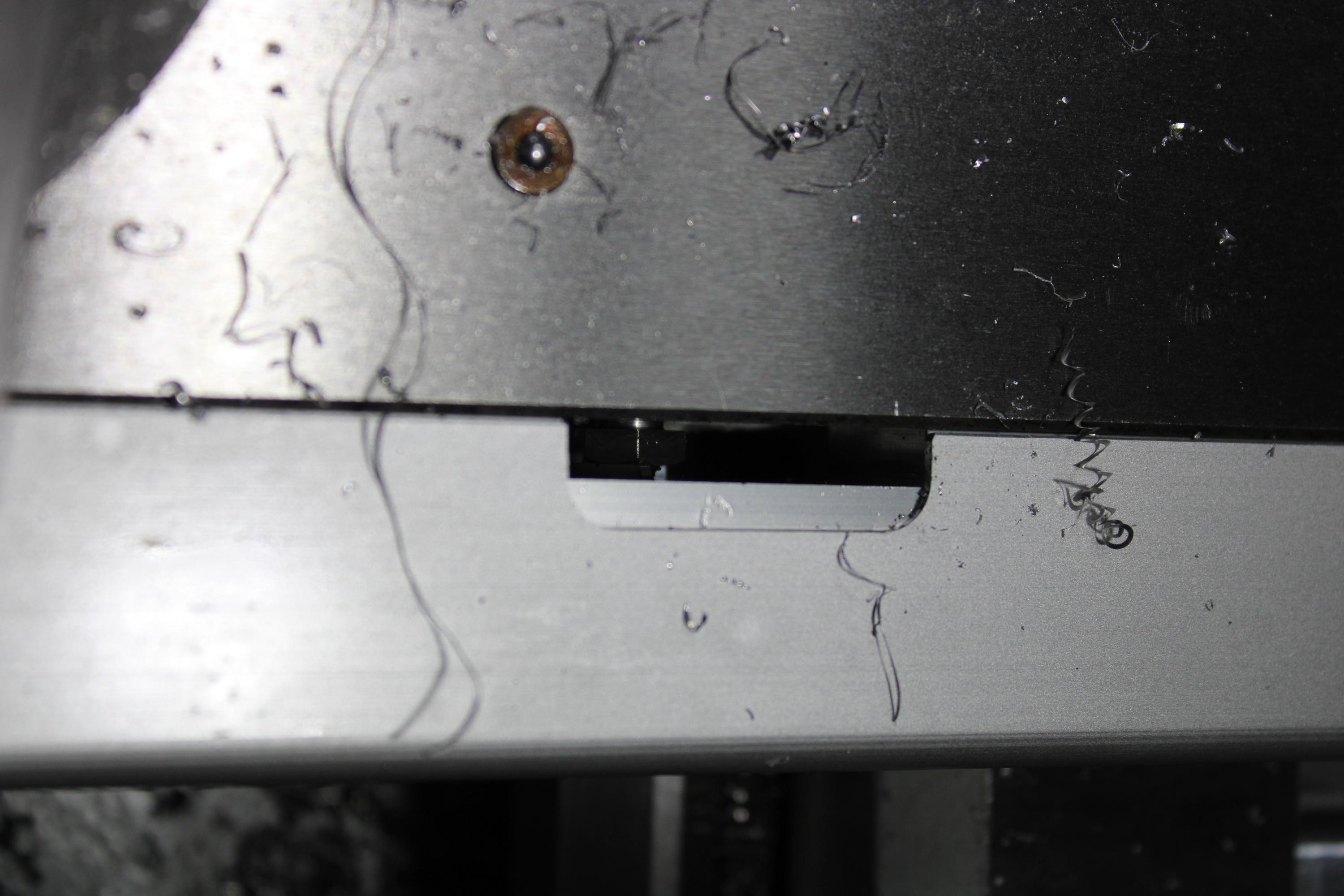
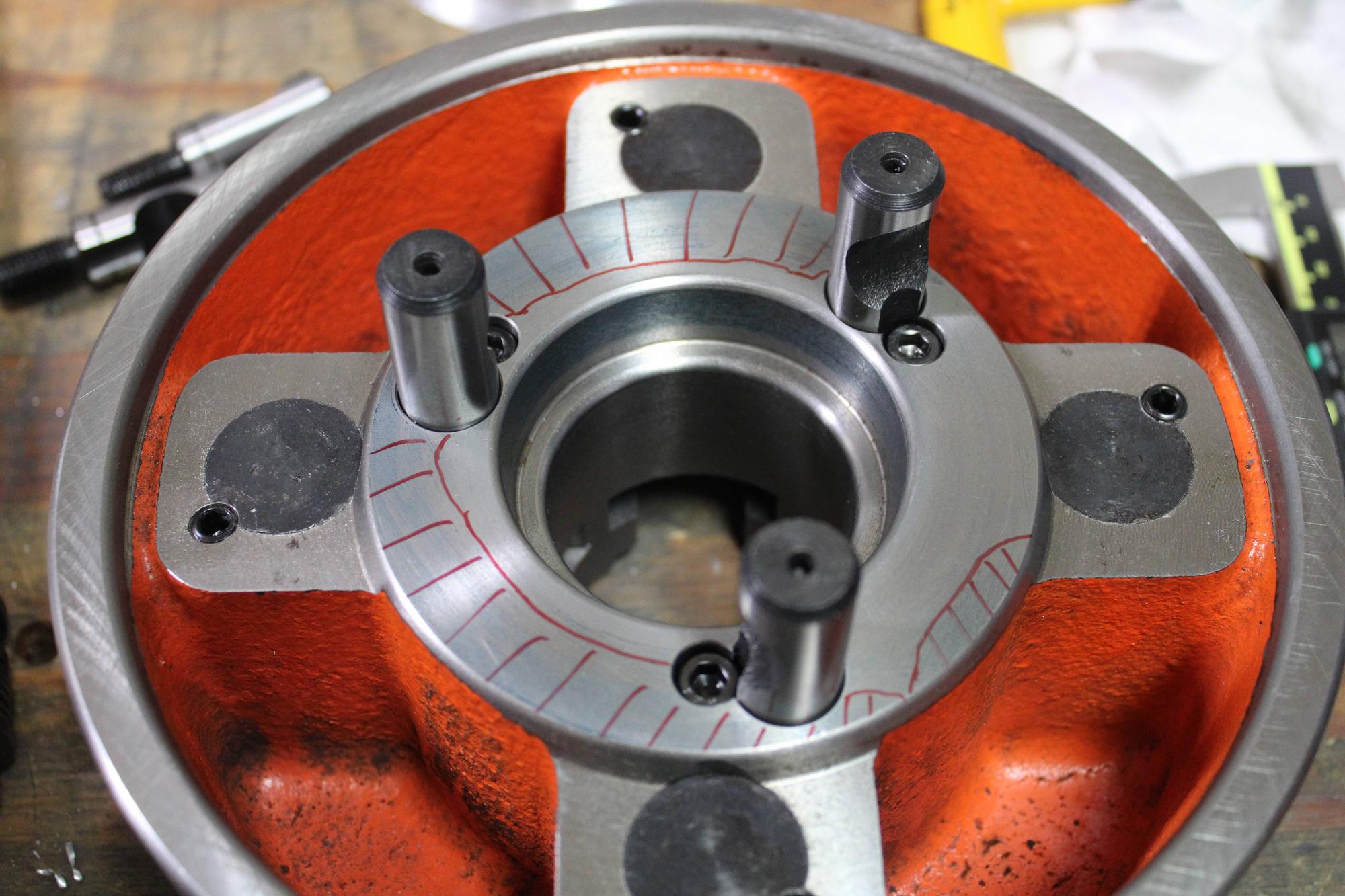
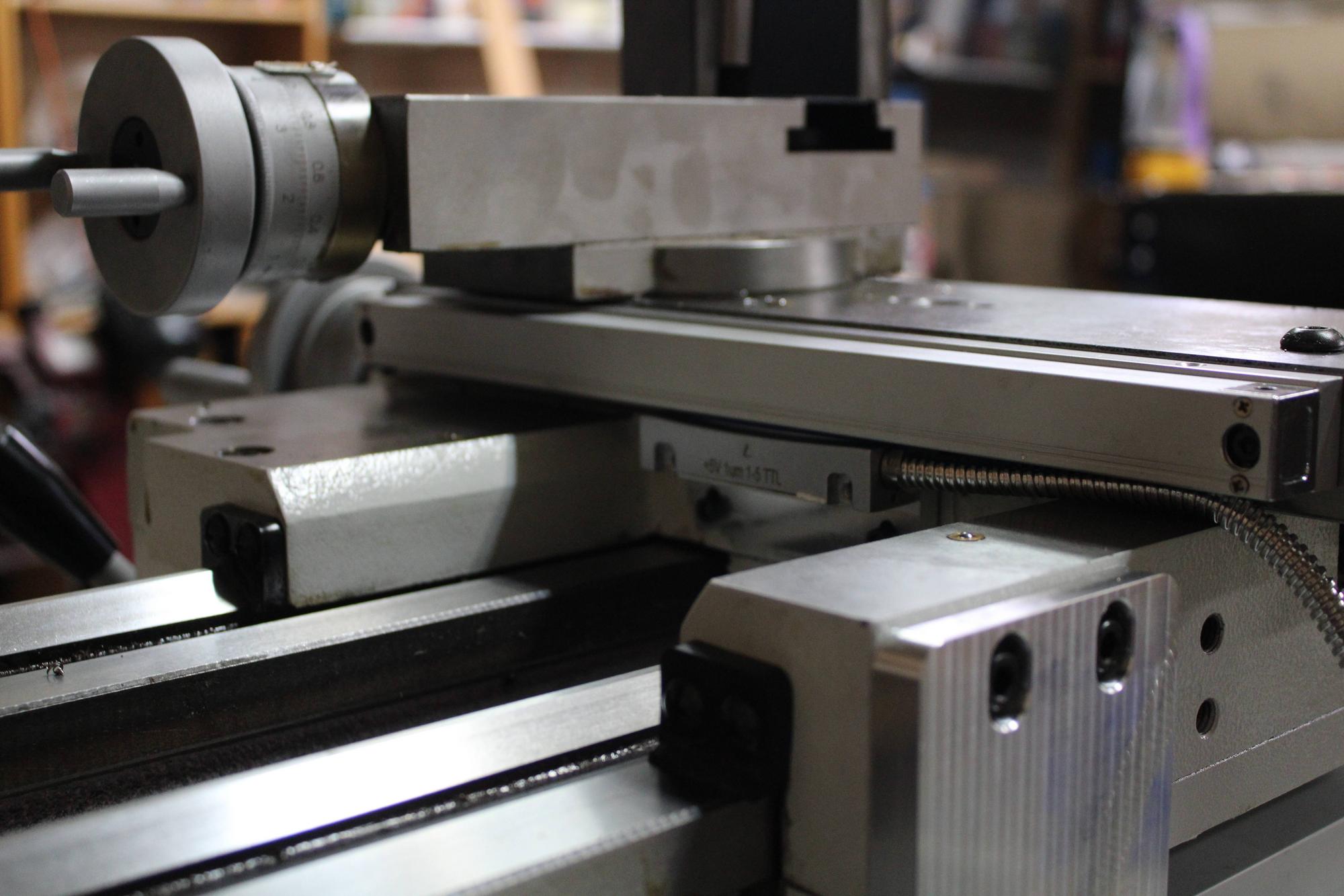
I pulled the cross slide off and stuck it in the mill to drill and tap the holes for mounting the scale. It came off very easily, just one screw and slide it off! In the mill, I used 1-2-3 blocks to hold it up and lightly clamped it with the vise. I used a piece of scrap aluminum to try to protect the ways. This was very straightforward and everything went fine!

yl7l2gK.jpg


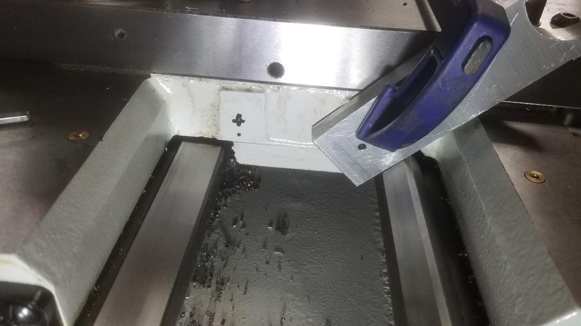
It looks like it has a steel insert where the screw goes to attach it to the lead nut. That seemed like a nice touch to me. Also, I am no expert on scraping, but these ways seemed to have the scraping done a little bit deep.
Fnir0wb.jpg


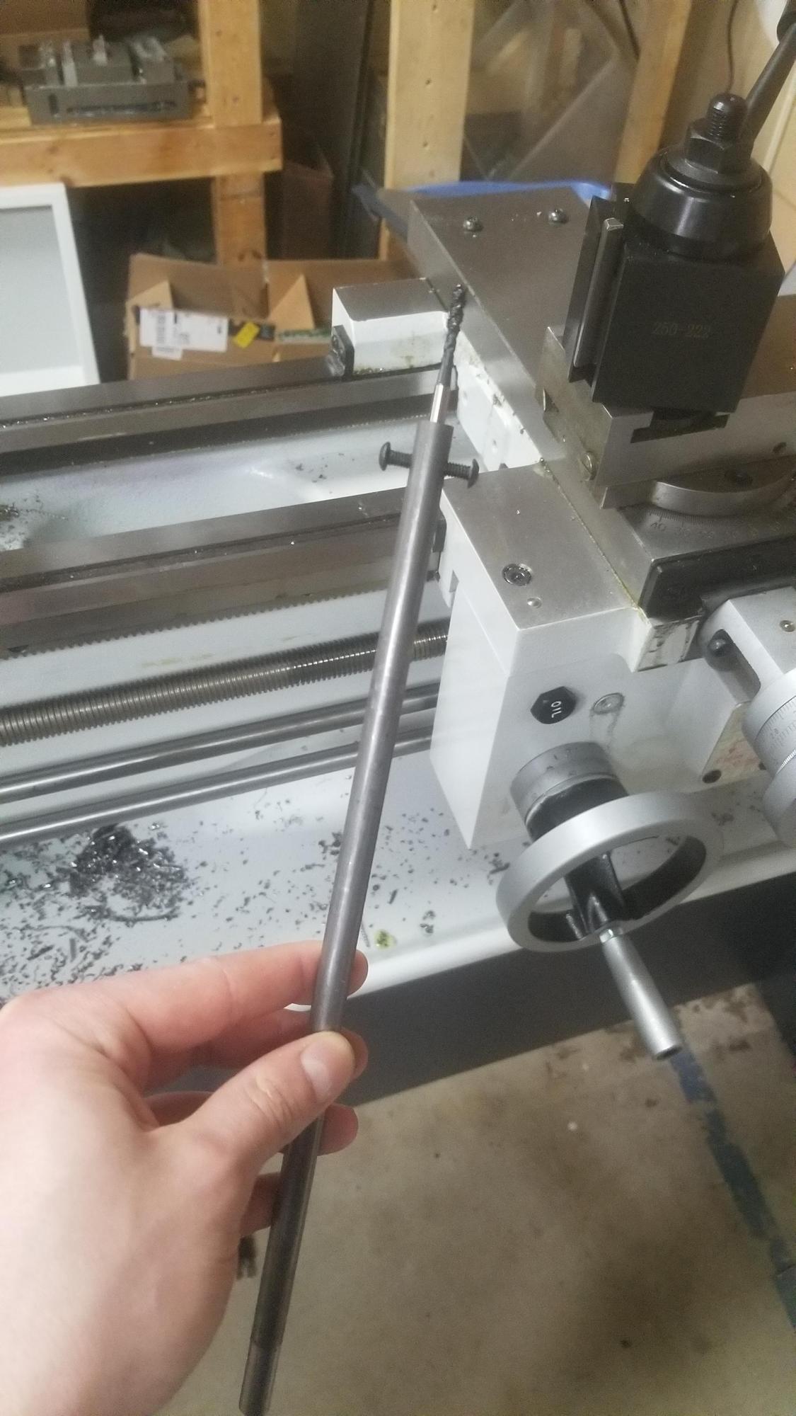
Getting the carriage drilled and tapped was a bit more difficult just because there was no room and I couldn't reach it. I had to make a quick drill extension and drill guide, then convert it into a tap extension. Once those were done, it went surprisingly well and the holes lined up just as they should.

LrVak3u.jpg


RRMG0Jl.jpg


I have had a cheap DRO on my mini mill before and the difference that it made makes me really excited to give this one a try.

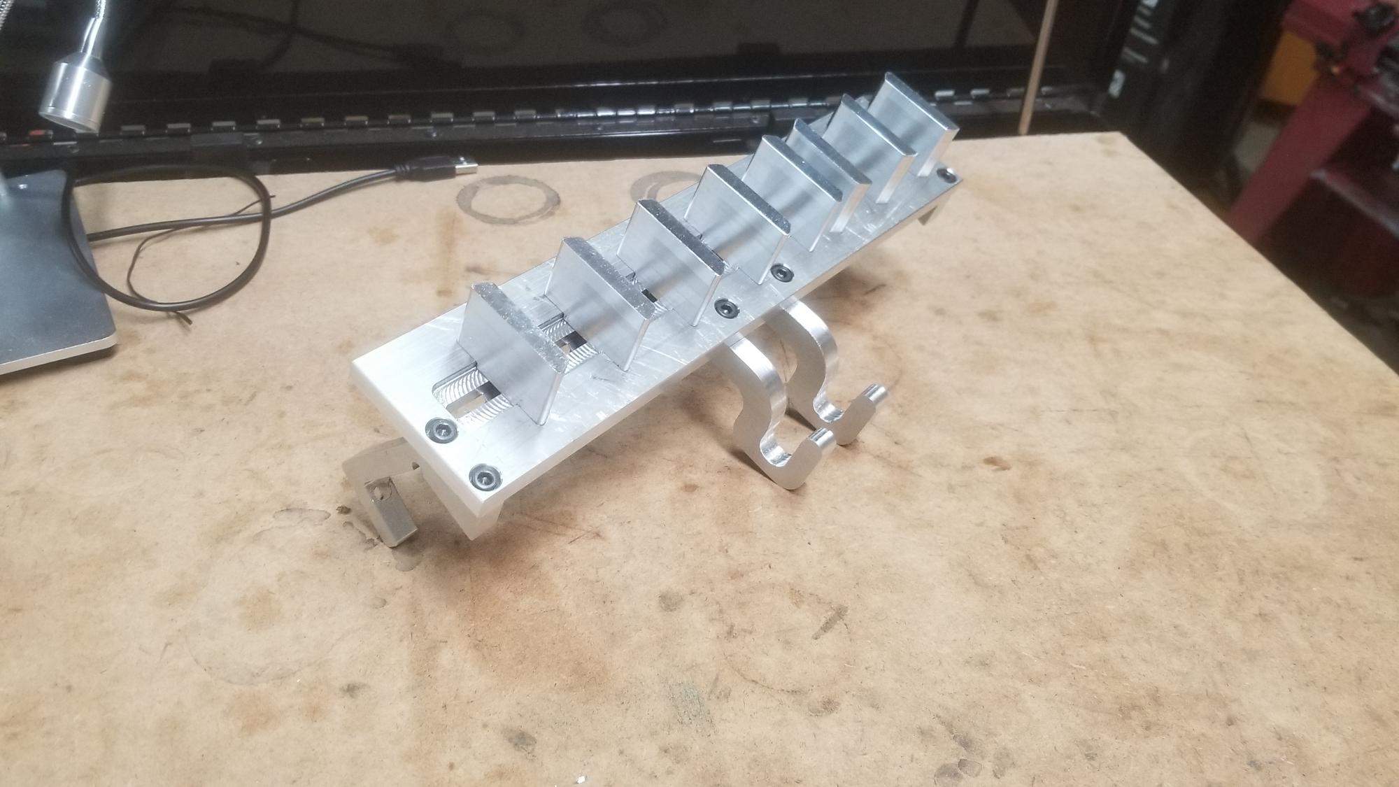
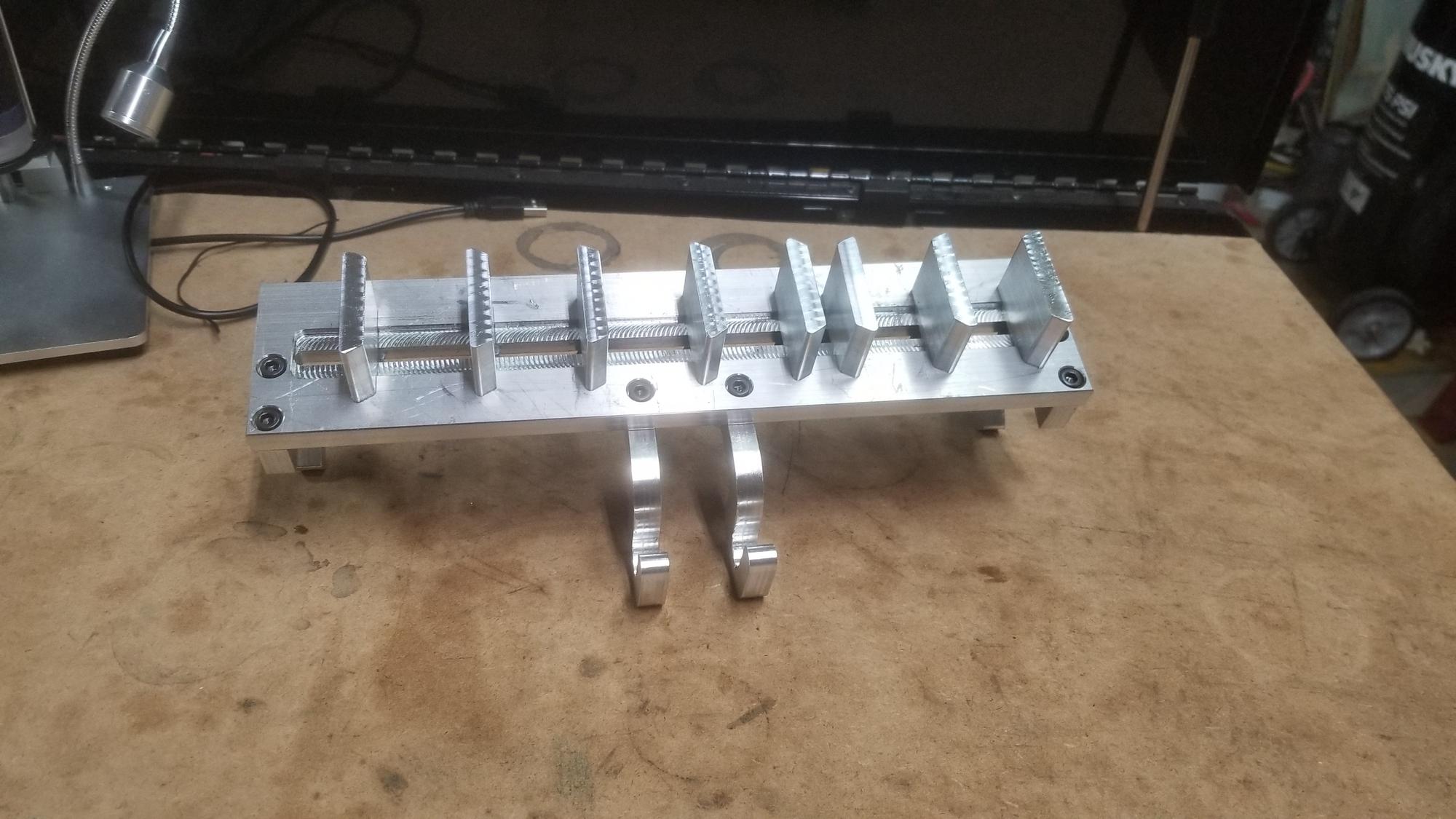
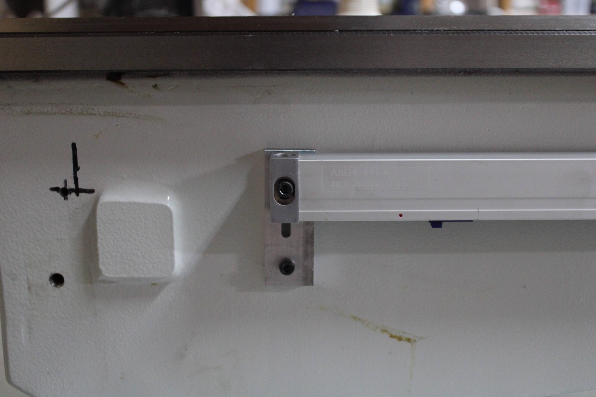
The Z axis gave me slightly more trouble, but again, not much. There are 2 raised portions along the side of the bed that look like they are there for mounting a DRO, but the DRO scales were not long enough to reach them. If I went to the left of the rear raised area, it would run into the splash guard mounting. If I went to the right of it, it would be mounting into the gap bed portion. The solution was just 2 little brackets that allow the scales to screw into a nut that slides in a slot on the bracket while the bracket screws into the bed directly. The 2 aluminum pieces that attach to the cairrage allow for vertical and horizontal adjustment. The brackets at the ends of the scale allow for adjustment as well. These combined made it rather easy to align once I had the holes drilled and tapped.

J7SBTKD.jpg


ldFqGBv.jpg


mr0kLw1.jpg


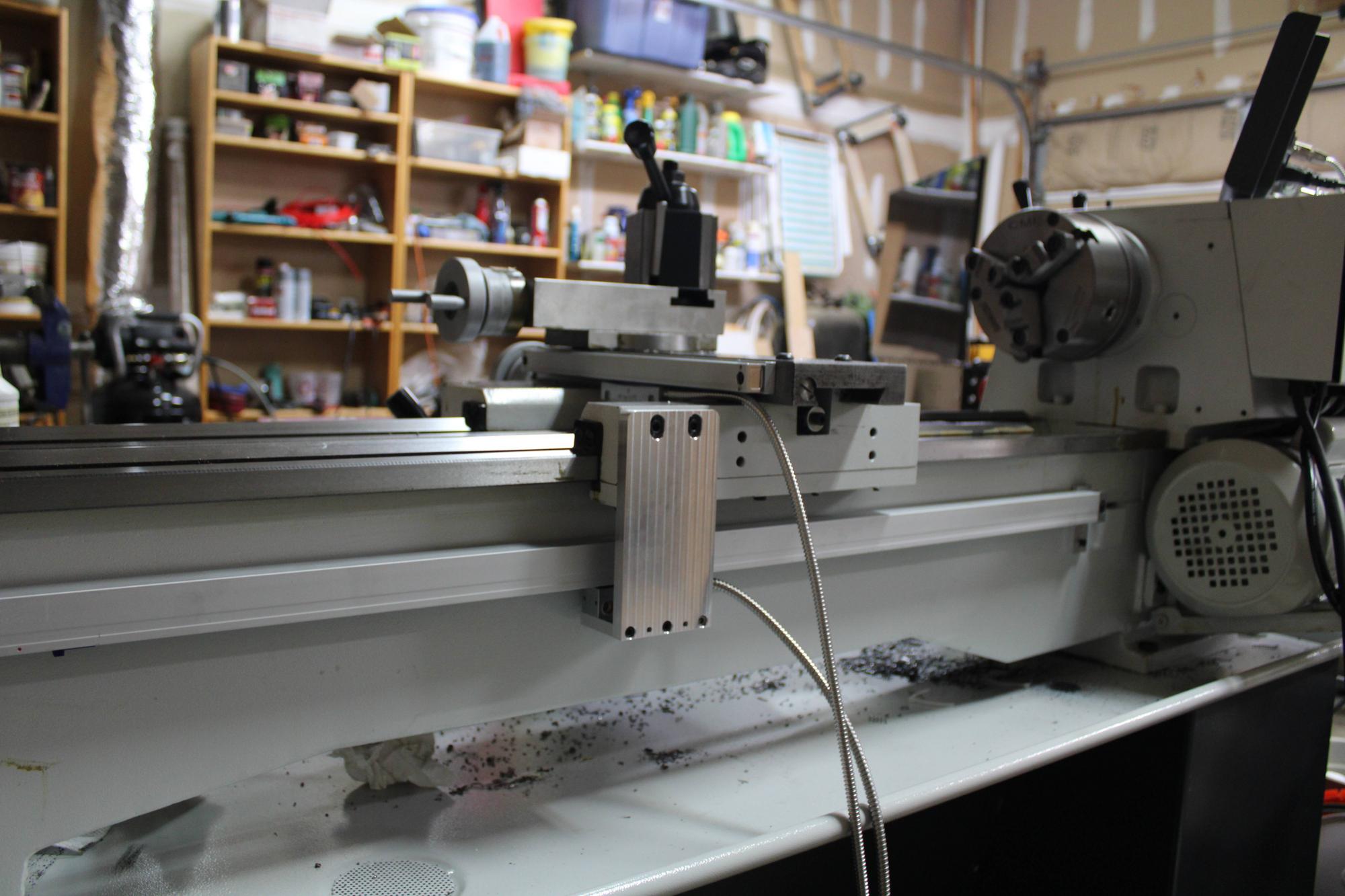
All that is left is to mount up the display, mount the guards, and secure the wires. Speaking of which, these cables with their metal cases are awesome! I need to figure out where to get them because they would be great for a number of other things.

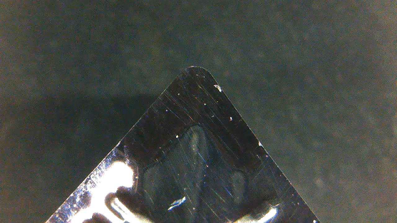
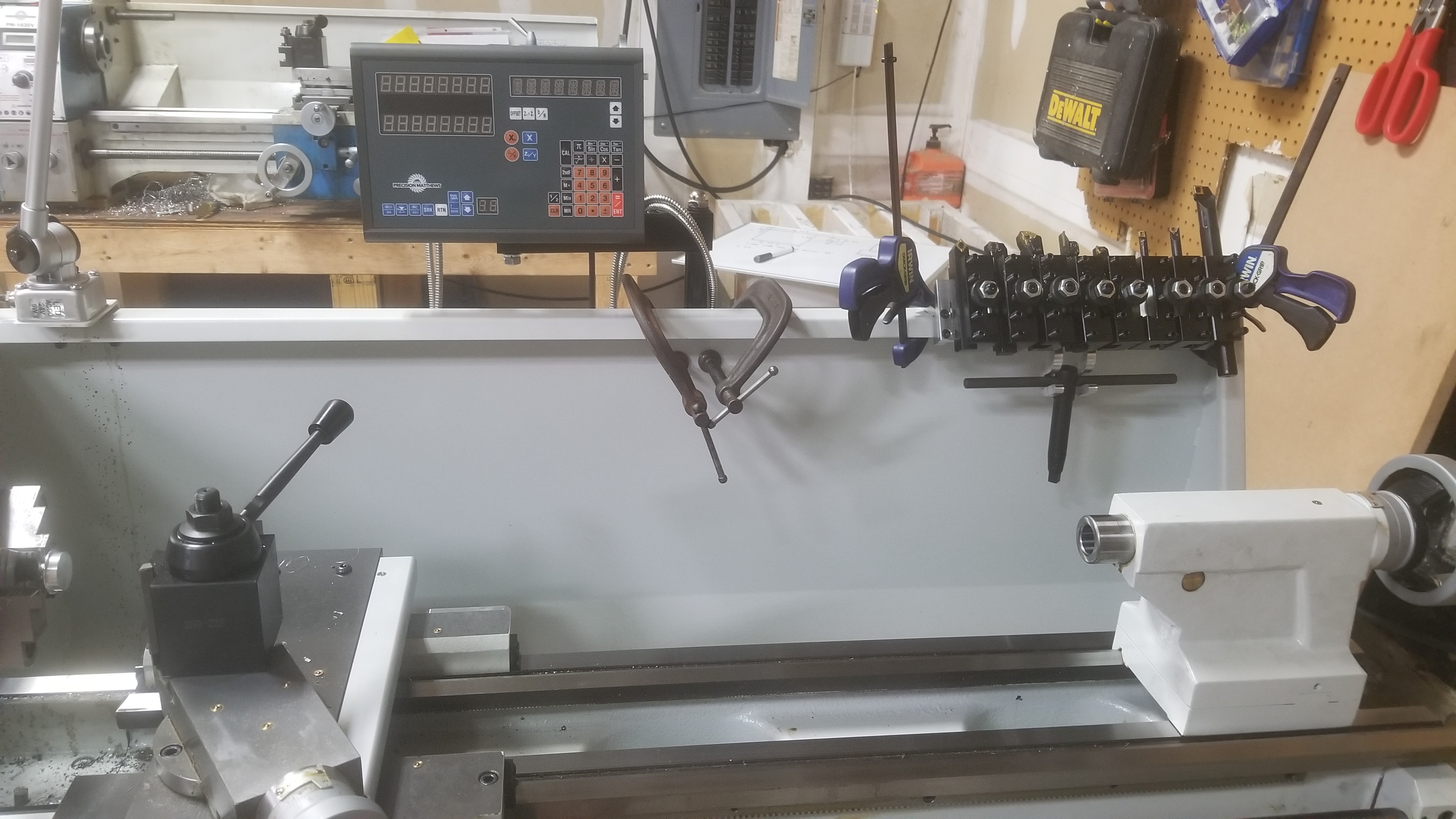
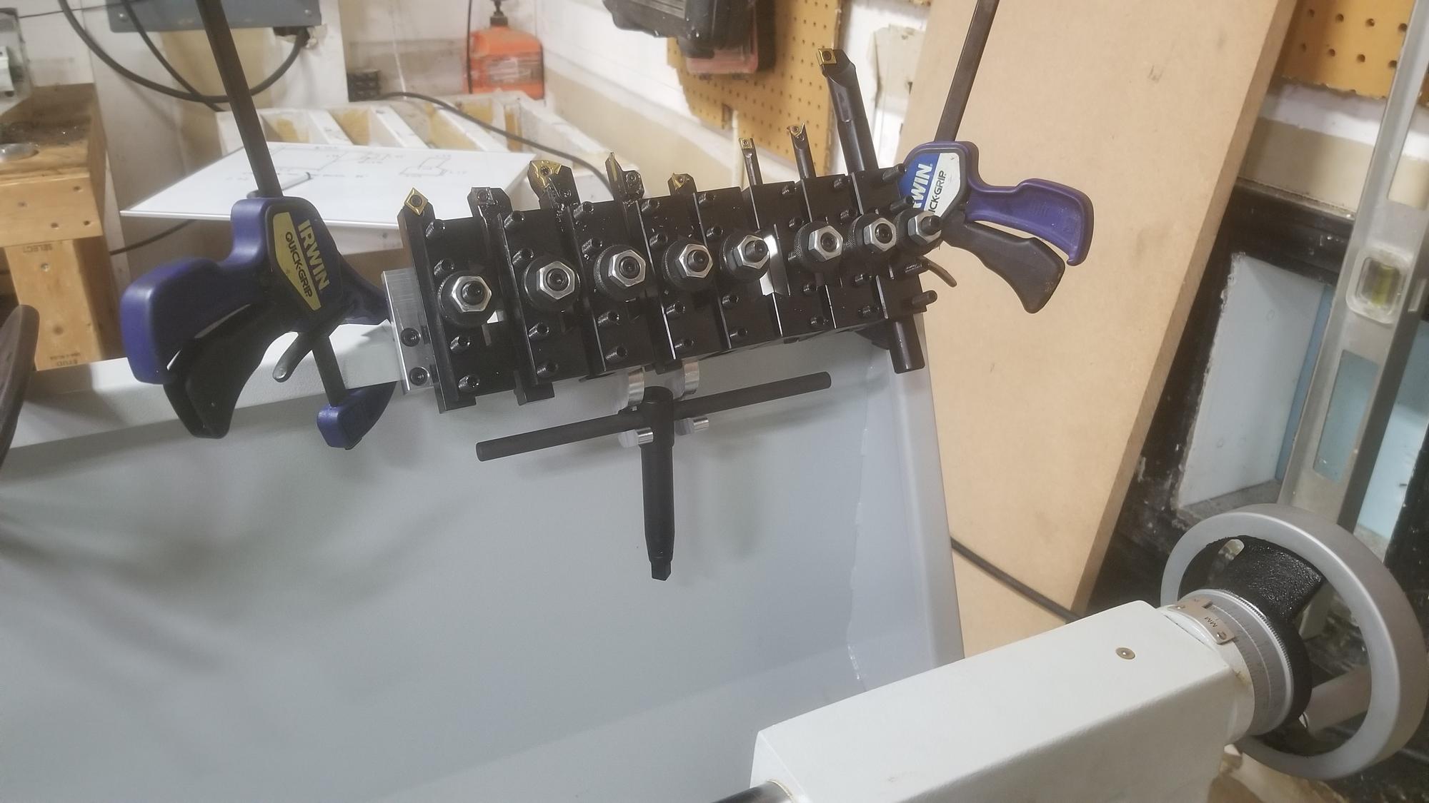
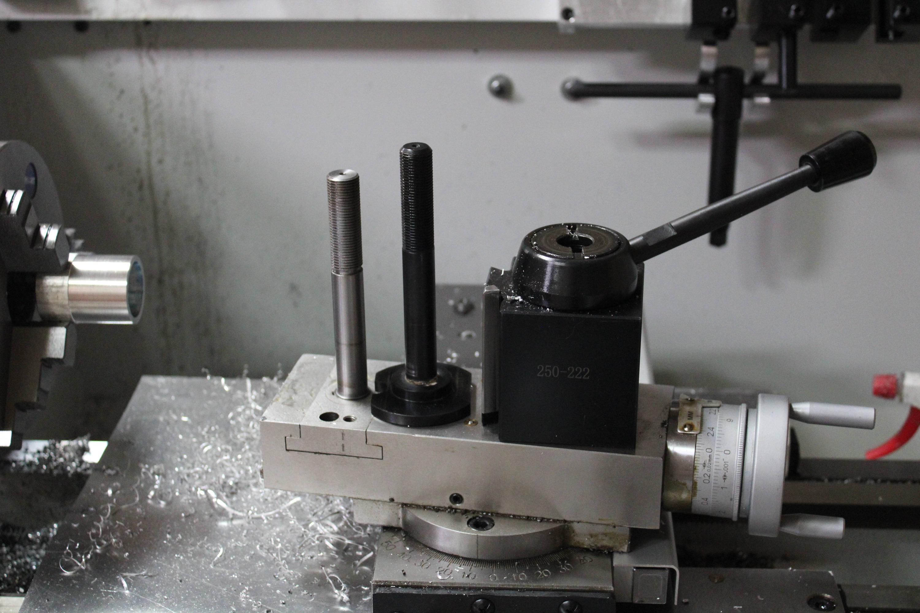
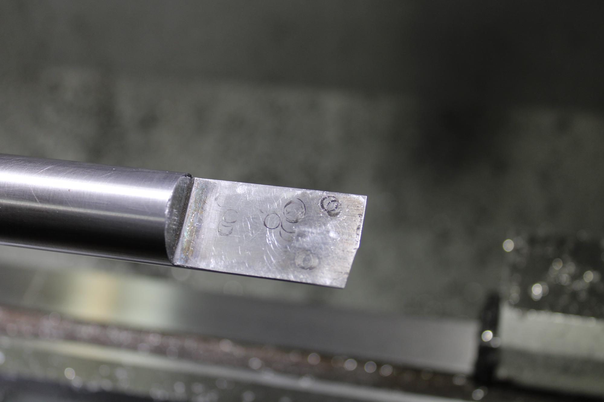
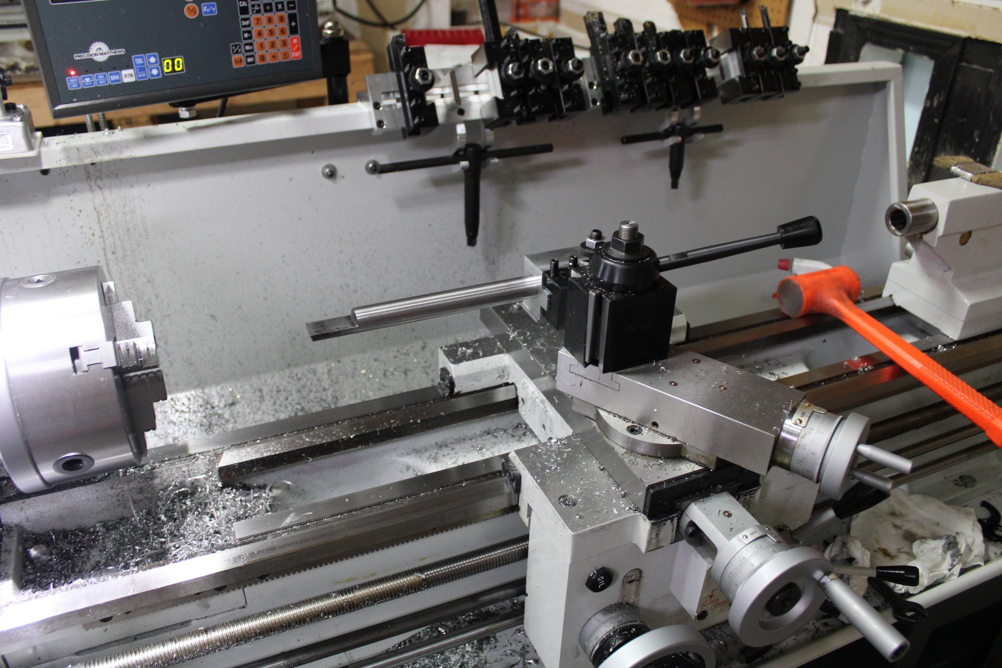
I also got their BXA insert kit and I am very happy with the quality. The tools have a great finish (Smooth finish rather than the chalky finish you often see) and when you tighten the inserts into place, you can feel it forcing them into the pocket the way they are supposed to.

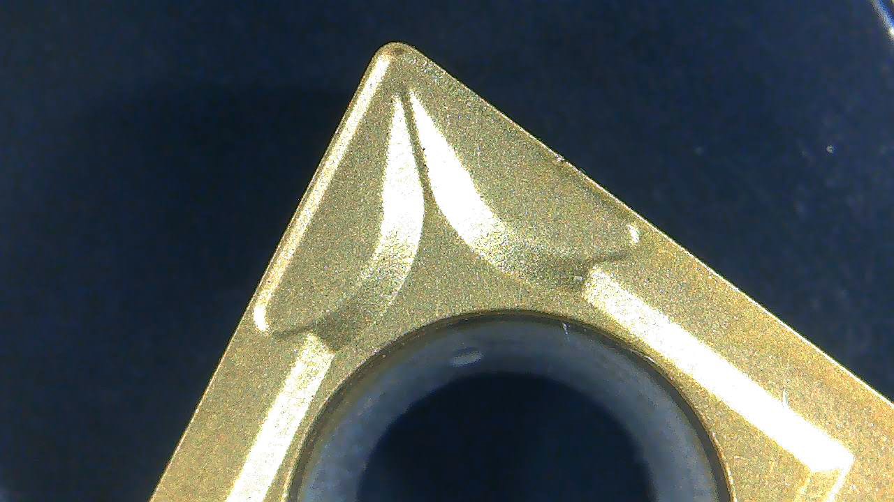
I had a look at the inserts under the microscope and they were looking good! The radius on the aluminum cutting insert looks like it will make an excellent finish.

lbZzz2M.jpg


fMxgAWi.jpg
 
The next add on a tool rack to keep all of the QCTP tool holders organized and nearby. I have always wanted to make a rack of some kind so they could stay on the machine, but in the past, I have just kept them on a table nearby. I drew something up in fusion and machined the parts over the weekend.

I wasn't sure how I wanted to space the tools out and I also didn't want to get stuck having tool holders that wouldn't fit because they had tools that were too large, so I made the spacing adjustable. The rack uses small dovetail portions that slide along a slot and are tightened using a screw from the other side. A nice bonus for this is that they are reversible so that boring tools and turning tools can face the same direction. The rack is tilted at 60 degrees so I can see the tools rather than just the backs of the holders. Now that i have put it on the machine though, 60 degrees seems a little bit steep. Next time, 55 or 45 would probably be better. I am already thinking a modification will be needed to add multiple decks for tools. I am only at 9 tool holders so far and I can only hang so many along the length of the back splash. I also added a hook to hold chuck keys hanging down below.

I am working on a similar rack that will hold tail stock tools like the live center, dead center, drill chuck and drill bits. I am thinking a few wrenches will also go on that one since it seems I am always looking for the one size that isn't handy.

I also can't decide where I want to put the display for the DRO. I didn't love placing it on the head stock because that would require reaching over the chuck to use it. I don't love where I put it on the back splash because it takes up space where tools will be going soon. If I put it too close to the chuck, it will be sprayed with oil and chips. Tough to decide...

E5vD9IX.jpg


5v3nSgc.jpg


8MeXv6m.jpg


q9HMtx2.jpg
 
I got the DRO and tool racks permanently mounted. I am sure they will move around as time goes on, but for now, this is where they will go. The DRO does get splashed a bit, but it doesn't seem like it will be a problem.

cRbTyu0.jpg


I made a new post for the tool post that fits into the base for the old tool post. This made a pretty big difference in ease of tightening down the tool post. It doesn't jump the way it used to with the old tool post post. Here is a picture of the new one compared to the old one.

YEZjPwD.jpg


I also modified the DRO mount a bit and made a small hex head screw to be able to lock the cross slide gib while the DRO is mounted. With the standard configuration, this is blocked, so I made a small slot in the mount and the cover and modified a standard M8 screw so it could be tightened with a 10mm wrench.

lo26ZkQ.jpg


All in all, I am loving this machine. Making parts with the DRO feels like cheating because it is so fast and easy to make accurate parts. I will be working on a BT30 spindle with it shortly and I am sure I will be adding more to it as well.
 
Working on the BT30 spindle with this machine is awesome. I don't normally break out the micrometers and try to hold tight tolerances, but with this spindle, you kind of have to. I roughed everything in, made a cut about .005" over, measured, made an adjustment, and each time it was accurate to a tenth. I thought I might have been tricking myself, but according to my inexpensive micrometers, the machine was "holding tenths all day long". It may be time to invest in some of those micrometers that can measure down to 50 millionths. You can't have a machine that is more accurate than your measuring tools.

The exterior of the shaft has 3 different threads and 2 bearing surfaces. It took a solid 20 minutes to do all 3 threads.

I need to order some longer drills to drill out the middle of this shaft. Until then, the next thing to work on is the housing.

1vELjFt.jpg


cBs5sji.jpg


OxzZEwL.jpg
 
Also, I mounted the light fixture to a steel shelf that I mounted to the wall behind the lathe. Seemed like a better option than mounting it to the machine itself. Nice and solid and no vibration of the light fixture.
That’s a great idea!!!
 
I have been working on a bit of a runout issue with the 4 jaw and was hoping someone might have some insight. The unbalance was pretty rough at the top low speed (780 RPM if I remember right).

I started with some prussian blue to try to check contact on the taper and on the spindle face. The taper contact looked fine, but the face wasn't. Here is the spindle face after attaching and removing the chuck.
FZ2RKuV.jpg


And here is the rear of the 4 jaw. There was contact along the outer edges in 2 of the 3 areas between the cams, and on one, there is no contact. The taper had good contact all the way around.
V3L2XoA.jpg


Here is the spindle face after checking the 3 jaw back plate. Contact was much better all the way around.
dLuU0Kf.jpg


I tried switching the cams between the 2 and there was a good bit of improvement. Here is the contact on the rear of the 4 jaw after swapping the cams. It was tough to get it to show up in the picture, so I highlighted the blued areas with sharpie. There is still good contact in 2 of the sections, but not quite so good in the third.
hgtqjwM.jpg


So the questions:
Can the cams affect the fit of the chuck?
Any idea about how to improve the runout on the 4 jaw? What would be an acceptable amount?
 
Also, unrelated, but I need to bore a .875" hole about 8.5" deep. I made a D bit to do it and a little block to hold it in the tool post. I reamed the toolpost block with the reamer and I was blown away by how well it worked. The bore finish was phenomenal and it was as close to perfect size as I can measure. I don't know why I waited so long to try one of these, it was so easy.

P1Lzhz0.jpg


ybMR3GE.jpg


Rfd4zki.jpg


b4ffCxj.jpg
 
Back
Top