

-
Welcome back Guest! Did you know you can mentor other members here at H-M? If not, please check out our Relaunch of Hobby Machinist Mentoring Program!
You are using an out of date browser. It may not display this or other websites correctly.
You should upgrade or use an alternative browser.
You should upgrade or use an alternative browser.
New PM-25MV Mill
- Thread starter shooter123456
- Start date
- Joined
- Mar 26, 2018
- Messages
- 2,724
I am thinking I will sand the sheets to a brushed finish, maybe around 800 grit sandpaper. I don't want to make them shiny and then have them look rough as soon as a chip scratches them, but I also think they will wear better with a surface that slides easier.
I usually opt for a fine scotch-brite finish by making small circular scrubbing motions across the whole surface. It hides scratches quite well in all directions.
- Joined
- Jan 20, 2016
- Messages
- 602
I have been working on the 4th axis brake design while I figure out how to proceed with the machines electronics. I built a new control computer, but I got the wrong type of hard drive for it... So there isn't much to do on that front until the new one gets here.
The brake is a simple pneumatic brake, similar to what you might find on a car. It uses a 2 stage air cylinder to actuate, then is released by one stage that works in both directions. I haven't decided what to use for a brake pad material, but perhaps some kind of rubber or plastic. I will use oilite bushings and ground guide rods to keep everything aligned.
The cylinder is an adjusted version of the one used for the draw bar. It should be able to get a few hundred pounds of clamping force which should be more than enough to hold the 4th axis in place. Also, the brake disk is slotted because thats how they are on the race cars and they look cool. Here are a few of the pictures designs.
Here is the whole mechanism.
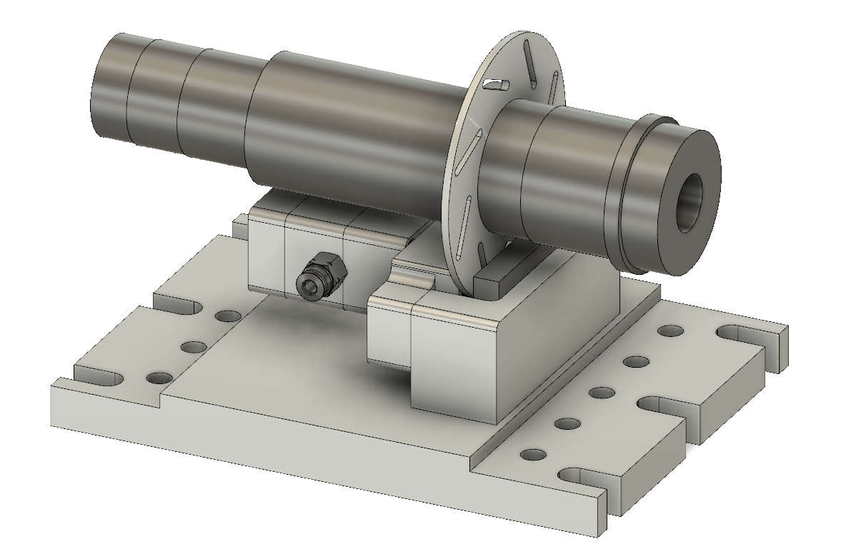
Here is the brake with the cylinder extended. It only moves about .1" to lock the 4th axis in place.
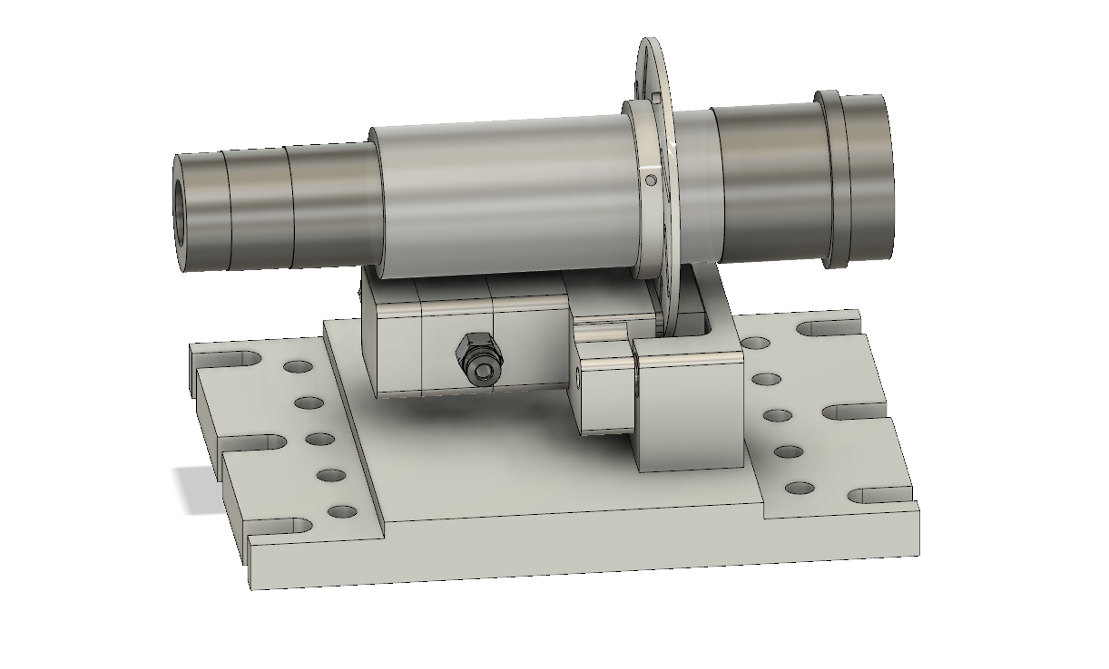
And here is the cylinder and brake by itself. The design got a little more complicated than I intended, but it seems like it will work.

The brake is a simple pneumatic brake, similar to what you might find on a car. It uses a 2 stage air cylinder to actuate, then is released by one stage that works in both directions. I haven't decided what to use for a brake pad material, but perhaps some kind of rubber or plastic. I will use oilite bushings and ground guide rods to keep everything aligned.
The cylinder is an adjusted version of the one used for the draw bar. It should be able to get a few hundred pounds of clamping force which should be more than enough to hold the 4th axis in place. Also, the brake disk is slotted because thats how they are on the race cars and they look cool. Here are a few of the pictures designs.
Here is the whole mechanism.
Here is the brake with the cylinder extended. It only moves about .1" to lock the 4th axis in place.
And here is the cylinder and brake by itself. The design got a little more complicated than I intended, but it seems like it will work.
- Joined
- Mar 25, 2013
- Messages
- 4,613
This looks like an awesome design. Another thing you might consider is to use a hydraulic mountain bike brake setup. It would be easy to build a cylinder to convert air pressure to a much higher hydraulic pressure with different piston sizes. You could also borrow the disc although the diameter may be too large for this application.

Hard to beat for $15. Very small . You could mount the air/oil conversion cylinder remotely to save table space.
Robert
Hard to beat for $15. Very small . You could mount the air/oil conversion cylinder remotely to save table space.
Robert
6-32s are well known to be troublesome when tapping. The minor diameter is too small compared to the major diameter and the result is a weak screw and tap.Tapping #6's can be a challenge. I try to design stuff with #8 at minimum.
R
If you go to a 6-40 UNF you'll have less of a problem.
Sent from my Pixel XL using Tapatalk
- Joined
- Jan 20, 2016
- Messages
- 602
I actually considered that a while ago, but a few things stopped me.This looks like an awesome design. Another thing you might consider is to use a hydraulic mountain bike brake setup. It would be easy to build a cylinder to convert air pressure to a much higher hydraulic pressure with different piston sizes. You could also borrow the disc although the diameter may be too large for this application.
View attachment 300919
Hard to beat for $15. Very small . You could mount the air/oil conversion cylinder remotely to save table space.
Robert
1. I have never worked with hydraulics before and I wanted to avoid adding another new thing to an already complex (for me at least) project.
2. I read from someone who adapted a bike brake for his 4th axis (Simpson iirc) and he said the caliper needed a lot of work to get it to work well enough.
3. I figured it would take just as much time to figure out how to get the bike brake to work as it would to design my own.
4. I like designing and making my own parts as much as (or more than) the final result.
5. Space is limited and I couldn't tell if the brake would fit.
I think using one as a spindle brake might be a better fit. It could help slow the spindle down faster if I want to speed up tool changes once the ATC is up and running.
I appreciate the input!
- Joined
- Mar 25, 2013
- Messages
- 4,613
Those are all good points. I have some experience with these brakes. As a point of information the caliper is about 1" x 1.5" x 2.5". The pads are removable. The motion seems to be fairly precise. To adjust the caliper location, you actuate the caliper so it is locked to the disc, then lock down the holding screws. Pretty simple. I wonder if the other guy was using a mechanical caliper which is less precise?
How large in diameter do you envision your air cylinder? Double action is a good idea. I assume the 4th axis will need substantial braking force to prevent motion by the cutting tool? I would be concerned that a narrow radius disc would not provide the needed leverage with either setup?
Robert
How large in diameter do you envision your air cylinder? Double action is a good idea. I assume the 4th axis will need substantial braking force to prevent motion by the cutting tool? I would be concerned that a narrow radius disc would not provide the needed leverage with either setup?
Robert
- Joined
- Mar 26, 2018
- Messages
- 2,724
Also, the brake disk is slotted because thats how they are on the race cars and they look cool.
Love the design justification
")
Looking great!
- Joined
- Jan 20, 2016
- Messages
- 602
I don't recall what kind of brake he was using exactly, but he actuated it with a small air cylinder and lever, so that may have been mechanical. The thing that worried me is that any wiggle in the brake could lead to chatter in the cut.Those are all good points. I have some experience with these brakes. As a point of information the caliper is about 1" x 1.5" x 2.5". The pads are removable. The motion seems to be fairly precise. To adjust the caliper location, you actuate the caliper so it is locked to the disc, then lock down the holding screws. Pretty simple. I wonder if the other guy was using a mechanical caliper which is less precise?
How large in diameter do you envision your air cylinder? Double action is a good idea. I assume the 4th axis will need substantial braking force to prevent motion by the cutting tool? I would be concerned that a narrow radius disc would not provide the needed leverage with either setup?
Robert
The cylinder I designed as a .75" bore, with .3649in^2 of usable surface area. The brake disk is 4" in diameter and the center point of the clamp is at 3.5". I am not positive how the physics there works (and my knowledge of the other physics is limited to 2 college classes, so it might be wrong as well) but my math says:
.3649in^2 * 2 * 100 PSI = 72.98 lbs
72.98 lbs * 4.45 (newton conversion, this could be wrong) = 324.8N
Coefficient of friction for aluminum on aluminum is 1.05 (may not need a pad in that case, not sure) so 324.8 * 1.05 = 341N
1.75" (radius of brake disk at center of clamp) = .0445 m
341N * .0445m = 15.2Nm
I am not sure if tangential cutting force is the correct force to use to determine how much force the machine must resist during a cut, but even the heaviest cuts I might take were around 20 lbs of force. Guessing the largest part I might work on is 4", that translates into 4.5Nm of torque.
I am not sure how much the thickness of the brake disk will play into the equation since all it does is translate the holding force from the brake to the spindle. As long as the force isn't so great that it crumples, I figured it would suffice.