- Joined
- Sep 22, 2010
- Messages
- 7,223
Posted with permission of the author:
From: Mike Rauchle <rauchle@ntd.net>
To: Nelson T. - The Hobby-Machinist <im_all_thumbz@yahoo.com>
Sent: Wednesday, May 1, 2013 5:58 AM
Subject: Re: Burke #4 Vertical Head Build
Nelson- Thanks for the comment, yes, go ahead and post it if you wish. Regards, Mike
On Tue, 30 Apr 2013 08:23:46 -0700 (PDT), "Nelson T. - The Hobby-Machinist" <im_all_thumbz@yahoo.com> wrote:
Your article on building a vertical head for the Burke #4 was great, and I was wondering if I could get your permission to post it on Hobby-Machinist.com for our members.
Thanks,
Nelson
-----------------------------------------------------------------------------------
Owner, SB Heavy 10L, Van Norman 12, Burke #4
http://www.Hobby-Machinist.com
In PDF format:
View attachment New Vertical Head for.pdf
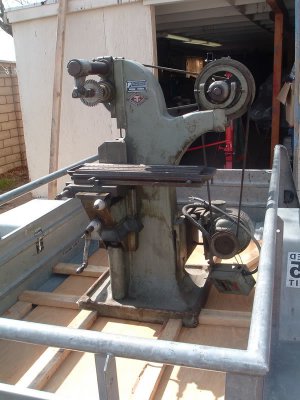
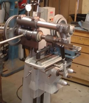
New Vertical Head for #1 Burke Horizontal Mill
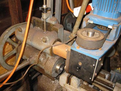
I slapped this vertical head together in a couple days about 10 years ago. It does a half assed job but the spindle is a fixed .500 bore, so it's kinda limited. Also could use more appropriate bearings. So, here we go with the upgrade to an R-8 spindle.
 2
2
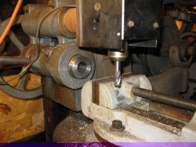
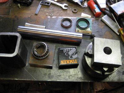
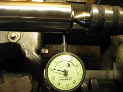
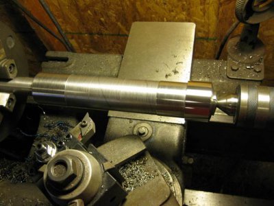
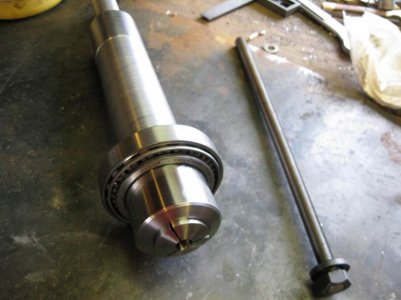
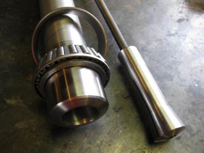
Raw materials rounded up, bored the shaft for the drawbar and the R-8 then used a collet with the live center to turn the bearing surfaces.
 4
4
 6
6
 8
8
 10
10
 12
12
Spindle Housing
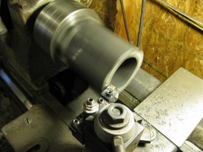
Spindle housing is A-50, 4 X 4 X .500 square tube, It will be oil filled with a sight glass and provisions to lube the top bearing
 14
14
 16
16
Spindle Seal
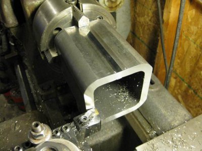
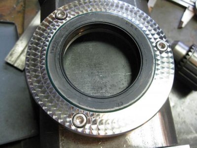
Stainless spindle seal retainer
 18
18
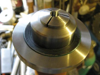
Jeweling/Engine Turn
I had some spare time on my hands today.
 20
20
 22
22
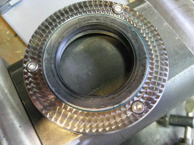
Key and Sight Glass
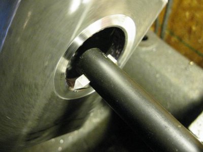
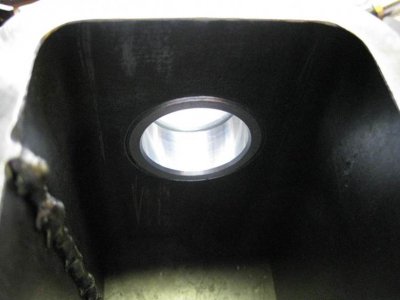
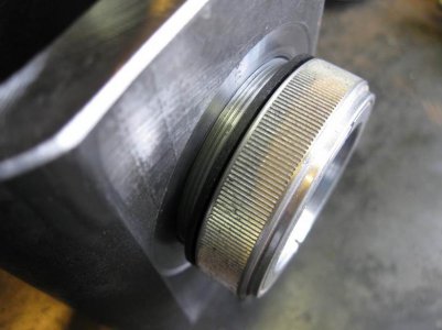
R-8 key, 5/32" ejector pin. Sight glass threaded into body of the spindle housing. This is the 1st time I have threaded A-500 material and it sucked. 1 7/8"-24 TPI. while boring,I started with HSS...tearing, carbide..tearing and chatter, HSS single point...tearing ...looked horrible. Tried different geometries,etc. just could not get a real clean cut.Maybe next time,any thoughts?
 24
24
 28
28
 30
30
 32
32
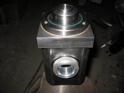
Seal Fit-up
I think I should have chosen a larger sight glass.
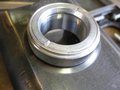
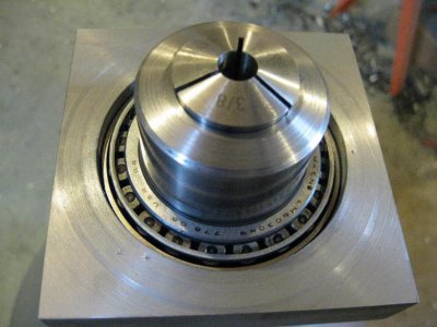
I do need to see in there as there will be a slinger to direct the oil to the upper race
I guess I'll find out what happens on power- up thru the giant sight glass
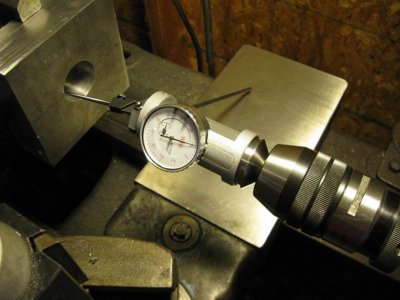
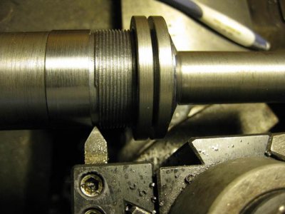
How long have co-ax indicators been around? I love this thing. Now, I need some ideas due to my poor planning. As you can see, I made 2 left hand threaded rings for pre-load adjustment, I need an idea to mechanically lock the top ring to the shaft after adjustment, I am drawing a blank right now. Thanks in advance, Mike
My first swing at it was a 4-40 cup point set screw, axially, however, when you tighten it, it takes out the lash in the threads in that spot and creates an uneven force against the inner race. Radial might be better or a keyed locking tab washer.
Bill[/QUOTE]
Bearing Retainer Lock
Sometimes you just have to stop over-thinking things and just try SOMETHING!
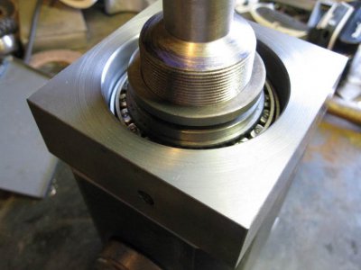
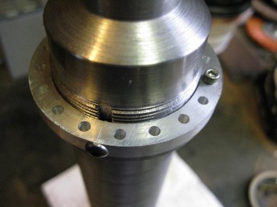
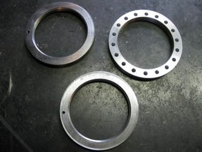
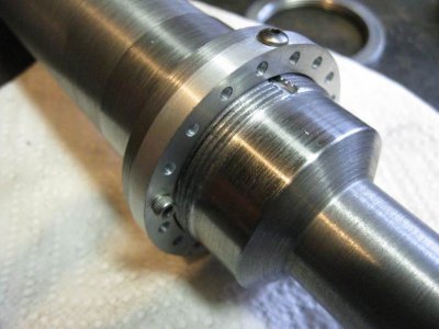
Done,well except paint.
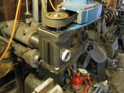
Had alot more time in this than I wanted but it was worthwhile. It works better than I expected and that's gratifying, runout is .0005. Not bad considering it was done on a 1929 SB, just shows what can be done with careful setup between centers. A little paint and call it good.
 54
54


From: Mike Rauchle <rauchle@ntd.net>
To: Nelson T. - The Hobby-Machinist <im_all_thumbz@yahoo.com>
Sent: Wednesday, May 1, 2013 5:58 AM
Subject: Re: Burke #4 Vertical Head Build
Nelson- Thanks for the comment, yes, go ahead and post it if you wish. Regards, Mike
On Tue, 30 Apr 2013 08:23:46 -0700 (PDT), "Nelson T. - The Hobby-Machinist" <im_all_thumbz@yahoo.com> wrote:
Your article on building a vertical head for the Burke #4 was great, and I was wondering if I could get your permission to post it on Hobby-Machinist.com for our members.
Thanks,
Nelson
-----------------------------------------------------------------------------------
Owner, SB Heavy 10L, Van Norman 12, Burke #4
http://www.Hobby-Machinist.com
In PDF format:
View attachment New Vertical Head for.pdf
New Vertical Head for #1 Burke Horizontal Mill
I slapped this vertical head together in a couple days about 10 years ago. It does a half assed job but the spindle is a fixed .500 bore, so it's kinda limited. Also could use more appropriate bearings. So, here we go with the upgrade to an R-8 spindle.
 2
2Raw materials rounded up, bored the shaft for the drawbar and the R-8 then used a collet with the live center to turn the bearing surfaces.
 4
4 6
6 8
8 10
10 12
12Spindle Housing
Spindle housing is A-50, 4 X 4 X .500 square tube, It will be oil filled with a sight glass and provisions to lube the top bearing
 14
14 16
16Spindle Seal
Stainless spindle seal retainer
 18
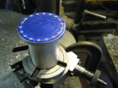
18Jeweling/Engine Turn
I had some spare time on my hands today.
 20
20 22
22Key and Sight Glass
R-8 key, 5/32" ejector pin. Sight glass threaded into body of the spindle housing. This is the 1st time I have threaded A-500 material and it sucked. 1 7/8"-24 TPI. while boring,I started with HSS...tearing, carbide..tearing and chatter, HSS single point...tearing ...looked horrible. Tried different geometries,etc. just could not get a real clean cut.Maybe next time,any thoughts?
 24
24 28
28
 30
30 32
32Seal Fit-up
I think I should have chosen a larger sight glass.


I do need to see in there as there will be a slinger to direct the oil to the upper race
I guess I'll find out what happens on power- up thru the giant sight glass
How long have co-ax indicators been around? I love this thing. Now, I need some ideas due to my poor planning. As you can see, I made 2 left hand threaded rings for pre-load adjustment, I need an idea to mechanically lock the top ring to the shaft after adjustment, I am drawing a blank right now. Thanks in advance, Mike

My first swing at it was a 4-40 cup point set screw, axially, however, when you tighten it, it takes out the lash in the threads in that spot and creates an uneven force against the inner race. Radial might be better or a keyed locking tab washer.
Bill[/QUOTE]
Bearing Retainer Lock
Sometimes you just have to stop over-thinking things and just try SOMETHING!


Done,well except paint.
Had alot more time in this than I wanted but it was worthwhile. It works better than I expected and that's gratifying, runout is .0005. Not bad considering it was done on a 1929 SB, just shows what can be done with careful setup between centers. A little paint and call it good.
 54
54


Last edited by a moderator:


