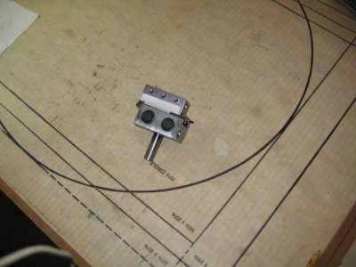
Next Project Boring Head

While I am often confused, and look like it, too, I don't like to be that way. Thinking about things in terms of forces helps me to understand how things work so I can control the process I'm working with. In our example here, knowing that doubling the speed will quadruple the CF is important to understand. When the bore has to be a certain size then it has to be that size. If using the proper cutting speed for that material results in chatter or vibration at the mill then reduce the speed; even a little bit can have a significant impact on how successful you are. OR you can switch from that heavy inserted carbide bar to a lighter cobalt bar and reduce the mass. Experienced machinists know all of this from experience or were taught by a wise mentor; hobby guys have to come at it by a different route, at least at first.
 
Was able to get back to the boring head today and got a fair amount done before the mid 90's temperature in the garage drove me inside.

I knew that I would never be able to drill the head and the pin separately and have the holes line up. So I put everything together and first drilled a hole for the 1/4-20 tap all the way through.
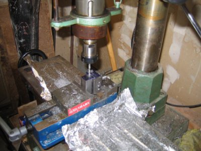
IMG_3730.JPG

Then I drilled just one end of the head to 1/4" and used this hole as a guide to tap the center pin.
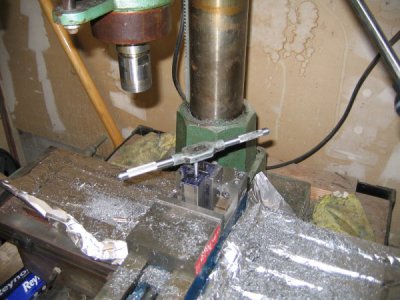
IMG_3731.JPG

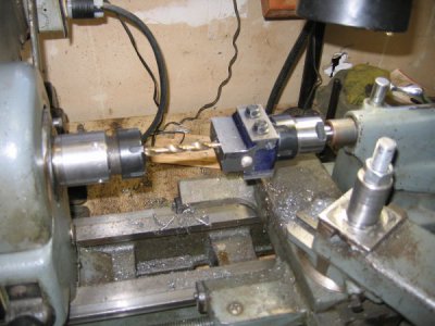
Then I drilled the other end of the head to 1/4." Screwed a long 1/4-20 machine screw through everything with a nylock nut on the end just tight enough to take out the play. Easy to turn the screw and the head moves smoothly in the body. There is just under .75" of travel. Over to the lathe to drill the center hole in the head. I decided to use 3/8 boring bars. Started the hole with a center drill
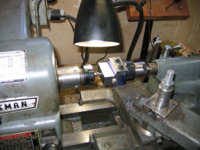
IMG_3734.JPG

and finished with 23/64 drill. I was planing to use a 3/8 end mill to finish off the hole but the hole ended up at 3/8" using the 23/64 drill.
IMG_3735.JPG

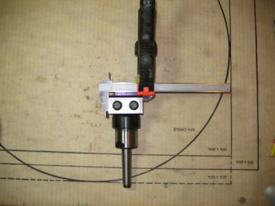
By now it was too hot to continue working in the garage even with my fan at full speed. Into the house. I do not have any means to accurately divide a circle into 50 segments and the marks on the end of the head would have been hard to see. I looked at my vernier caliper and thought that I could simply use it as a guide to mark the side of the head.
IMG_3736.JPG

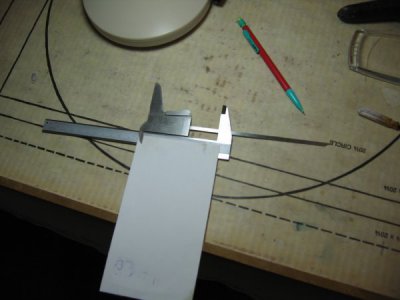
Well that didn't work too well trying to keep everything in place while I tried to hold a magnifying glass and scratch the lines. Next idea was to again use the caliper as a guide to mark the lines onto a piece of paper.
IMG_3737.JPG

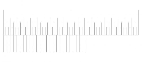
That didn't work either. Finally I went to sketchup and drew the lines and the vernier scale.
boring head scale.jpg

This worked. I was able to print this out and used double stick sailmakers tape to attached the drawing to the boring head. The sailmakers tape has really good holding power. I might put some clear lacquer over it to seal the paper so I can clean it
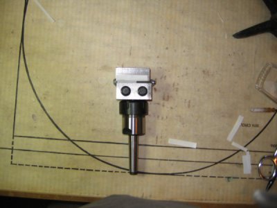
IMG_3738.JPG

Once attached I cut the scale in two with a sharp knife. The dimension lines are attached to the head and the vernier scale is attached to the body. Everything lines up. I can easily read to .001 and with effort to maybe ,0005. Still have more to do but I am getting there
 
I think that it is done.

IMG_3739.JPG

It is not pretty. In fact I think that I did a pretty lousy job making this boring head. It will probably be just fine for turning tapers on the lathe. Trying to bore accurate holes on the mill/drill is probably another story. Time will tell when I actually try to use it.
 
Question why do you think it won’t work. If you can adjust it constantly, you can use an indicator when you adjust the boring head.


Sent from my iPhone using Tapatalk
 
I might be being too harsh on myself. And I have never used one. The finish on the parts is pretty offal with lots of tooling marks and the dovetail fit is a little sloppy. Not precise at all. It takes a fair amount of effort to tighten the bolts to lock the head and the body together due to the sloppy fit on the dovetails. The design specs a 1/4" hole with a slot and 1/4" bolts to clamp the body to the head. I had to increase the hole to 3/8" and the bolts to 5/16 grade 8 flange bolts to get the force to tighten the bolts to a reasonable level. I plan to use 3/8 boring bars. When I drilled what I thought was going to be a slightly under size hole that I would then use a 3/8 end mill to bring up to size I inadvertently grabbed a 25/64 drill instead of the 23/64 drill. So one of the holes to hold a boring bar is 1/64" oversize. All in all it did not come out as nice as I had hoped for. In use it may function just fine.
 
mickri, it sounds like you are disappointed with the fit and finish but I give you a lot of credit for taking on what I view as a pretty complicated project I bet you learned a lot and I bet it will work just fine for turning tapers. Let us know. TK
 
Chuck, we all have projects like this - they're called Learning Experiences. No matter how experienced you get you will still have those projects that do not turn out exactly as planned. I have a box labelled the "Blunder Box"; I keep all the screwed up things that I tried to make and failed at. Keeps you humble, you know?

Like TK said, you have to keep things in perspective. This is a really ambitious project for a new guy to undertake and it came out functional and looks good. So what if it isn't perfect. I didn't exist until you created it and that means something.

There isn't a single guy here who hasn't messed something up - grabbed the wrong drill, turned a handwheel one time too many, read a micrometer wrong and the list goes on and on. Every time we mess up is a lesson learned and the next time we do better. If you ask me, I think you did just fine so take heart and know that you have a lot of company!
 
The reason why I asked is I’m thinking of using the design to make a ball turner. This way I can control the head size


Sent from my iPhone using Tapatalk
 
I have been using the boring head and it works well. One problem that has developed is the shank being held by a set screw. The set screw loosens up in use. Thinking about either using some Loctite or solder it in place with Stay Brite silver solder. The paper vernier scale is getting hard to read. Exploring ways to accurately mark the head and the body.
 
My Deckel cutter grinder has what amounts to cut down strips from a steel ruler facing each other and riveted to the tool body to adjust offset when sharpening cutters. Perhaps this might work for you?
 
Back
Top