Oh boy, you guys are gonna hate me.

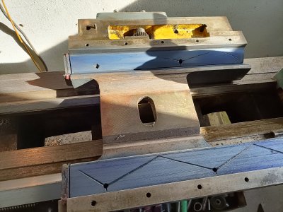
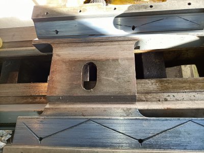
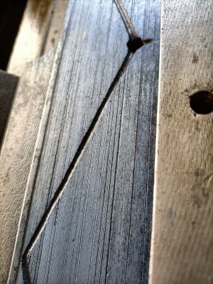
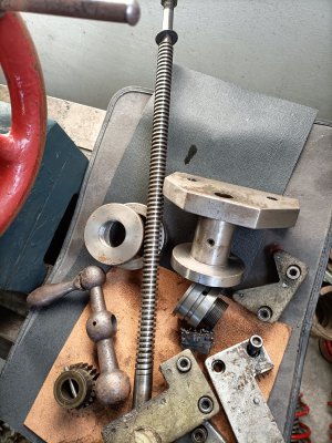
He is correct, if you set the tool at the centerline your cross-slide traveling in on an angle in and out will not matter. Think about a slant bed lathe it comes in and still works. Or a cut off tool on a screw machine. as long as the tool is set to the centerline at the end of the cut. We try to keep the saddle co-planer to the bed - front or head-stock end to tail-stock end by measuring the underside of the saddle where the carriage bolts on so the feed shaft and feed screw / half nut are aligned to the right height. As I explained by shimming the saddle up and using the rack pinion and rack clearance and measuring down from the top of the saddle flats above the dovetail with either a level on them and the bed or indicating the tops and moving the saddle front to back and indicating those clearance surfaces. Machine rebuilding is not rocket science. If you have common sense and take your time and ask people who have down it before it's simple. Now with you tube and being able to post photo's from experts online. You will be able to solve this problem. Where the issue lies is trying some new way and experimenting or listening to someone guessing at how to do it. That is where you will get yourself in a mess. Thanks VT for moving this into the rebuild section and as you said VT, many should learn from this thread as we help the OP.
 
You seem to have a problem with repeatability. And it seems that the saddle does not properly fit the bed ways. That lack of proper fit could show up as an uncertain position for the saddle in the x-axis (cross-slide direction).

It was suggested earlier to determine the bearing surfaces for the saddle on the bed ways. Given the extreme angle that the saddle seems to take, and the apparent nonrepeatability, this should be your prime objective. The saddle needs to have a consistent interface with the bed ways. It also needs as large a contact area as possible (distributed across the saddle extents). Once that is achieved, you will have good stiffness and good averaging of any way nonlineararity. Resurfacing the saddle as Richard mentions would achieve the broad contact that you need. But determining your current contact surfaces may shed some light on the issue.

Edit: also, if you can get a more sensitive level, you’d want to measure across the bed ways without the carriage supporting the level (e.g. on 123 blocks) to see if you can get the ways themselves straight without any possible influence of the saddle-bedway fit.
So I stoned the surfaces, and tried bluing and rubbing the saddle back in the bed, and I'm not really sure what I was expecting... I think the saddle is touching all across the bed, although the burs and bruises...
 

Attachments

  • IMG20211105125832.jpg
    IMG20211105125832.jpg
    4.7 MB · Views: 30
  • IMG20211105130953.jpg
    IMG20211105130953.jpg
    4.4 MB · Views: 28
  • IMG20211105131038.jpg
    IMG20211105131038.jpg
    4.3 MB · Views: 25
  • IMG20211105131027.jpg
    IMG20211105131027.jpg
    3.8 MB · Views: 26
I would say that the trapezoidal thread isn't worn out that much honestly
I am talking about the cross-feed screw and using the Green-Bay Mfg. pre-made. In the photo you just took. Look at the feed rack that is bolted under the way up to the far left. That portion is brand new as the carriage never allows the feed rack pinion gear never goes up there. Then compare the rack down toward the tailstock. I would bet a Euro $ that the rack is worn or it's teeth are sharp or pointed where the saddle is used the most as the ways up near the chuck are worn the most.
 
I have found some info for you. Specs are from a new machine. Your bed is worn and fortunately the head can be adjusted as it sets on 2 flat surfaces. You epoxy on the wear strips as the other fellow said with Rulon 142 or Turcite B or the other products I mentioned, scrape it to fit the unworn area on the tail stock end, replace or make a new cross-feed screw and nut you should have an OK machine or be able to sell it and buy a better one. http://vintagemachinery.org/pubs/182/25340.pdf
 
I
I am talking about the cross-feed screw and using the Green-Bay Mfg. pre-made. In the photo you just took. Look at the feed rack that is bolted under the way up to the far left. That portion is brand new as the carriage never allows the feed rack pinion gear never goes up there. Then compare the rack down toward the tailstock. I would bet a Euro $ that the rack is worn or it's teeth are sharp or pointed where the saddle is used the most as the ways up near the chuck are worn the most.
m sorry Richard I dont understand what you mean, do you mean the crosslide feeds crew?
 

Attachments

  • IMG20211105132414.jpg
    IMG20211105132414.jpg
    4.8 MB · Views: 22
From your photo's it looks at if the leveling screws are inside the foot or bases. You should have the base leveling screws setting on leveling steel plates. that would be 12.7 mm x 101.6 mm x 101.6 mm (1/2" x 4" x 4") with a 25.4 mm (1") x 3.175 mm deep (1/8") so the leveling screw sets into the hole. I could not find a maintenance manual for you model, but found these.


From your photo's it looks at if the leveling screws are inside the foot or bases. You should have the base leveling screws setting on leveling steel plates. that would be 12.7 mm x 101.6 mm x 101.6 mm (1/2" x 4" x 4") with a 25.4 mm (1") x 3.175 mm deep (1/8") so the leveling screw sets into the hole. I could not find a maintenance manual for you model, but found these.


I

m sorry Richard I dont understand what you mean, do you mean the crosslide feeds crew?
The in and out screw with the dials. The one that feeds the cross-slide in and out is called the cross feed screw. The picture that VT shows. Post # 52
 
The in and out screw with the dials. The one that feeds the cross-slide in and out is called the cross feed screw. The picture that VT shows. Post # 52
So yes it is that screw, I'd doesn't seem too worn and the backlash isn't that bad either, maybe 1mm tick on the dials...
Did you see the pictures I sent of the ways blued?
 

Attachments

  • IMG20211105132414.jpg
    IMG20211105132414.jpg
    4.8 MB · Views: 19
Yes, The saddle looks like a rocking chair I bet. Meaning it is convex or looks like the chair old people sit in and it rocks up and down. When you set it on a lathe it is trapped on the V ways and as you push it back and forth it rocks and looks super flat. Remember what I said about why there are pits or scratches in the cast iron? It was lapped flat with grinding grit or no oil so it lapped flat and the blue looks good. You only want 50% contact not 100% contact. If you had a straight edge and you lay it on the saddle ways I bet it will show they are convex.
 
Yes, The saddle looks like a rocking chair I bet. Meaning it is convex or looks like the chair old people sit in and it rocks up and down. When you set it on a lathe it is trapped on the V ways and as you push it back and forth it rocks and looks super flat. Remember what I said about why there are pits or scratches in the cast iron? It was lapped flat with grinding grit or no oil so it lapped flat and the blue looks good. You only want 50% contact not 100% contact. If you had a straight edge and you lay it on the saddle ways I bet it will show they are convex.
Unfortunately I have no straight edge, I'm only 24yo and I'm the first in the family coming Into machining so I don't have many of the tools I still need... I can try and make a straight edges on the Shaper.
 
Back
Top