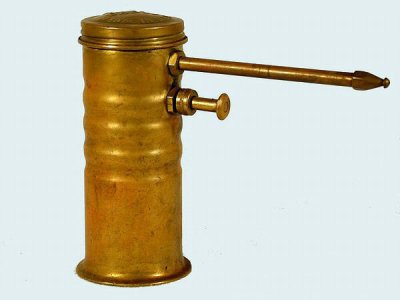
Trigger
View attachment 177676
View attachment 177726
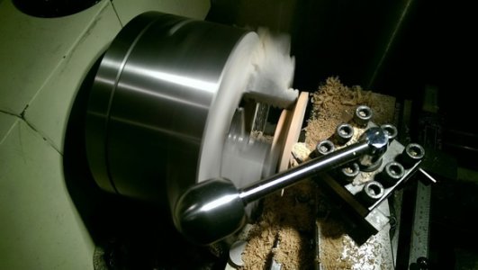
Starting the pump housing
View attachment 177774
View attachment 177777
Had to make a homemade drive dog for this. The housing is turned to fit the ID of the brass tubing that will be the container.
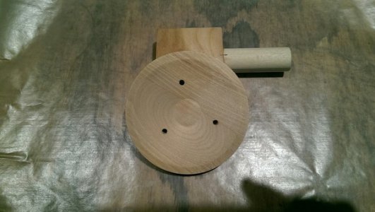
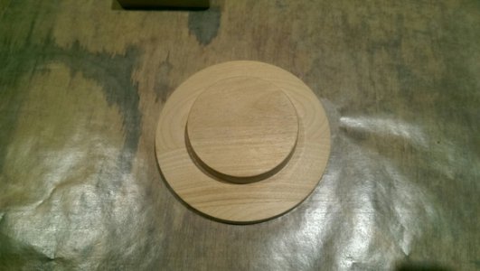
Next step is to mount in in a 4 jaw chuck and bore holes for the piston and the output tube.
Setup for reaming the pump housing:
View attachment 177780
It was good to do the boring on the lathe because I could drill ream and tap the threads accurately in the same line.
View attachment 177782
The large brass screws just mark the threaded holes for the pickup tube and the output. All the passages are now crossdrilled. I have to figure out the valving next.
Here is the brass tube segment.
View attachment 177785
I ended up cutting it with the portaband. Worked fine. I will finish the ends on the lathe or disc sander so it is really square and smooth. This will get soldered to the base after it is cast.
_____________________________
I made some progress!
View attachment 177787
View attachment 177791
View attachment 177793
View attachment 177798
View attachment 177800
I am very pleased so far. But will the trigger leak???
Next is casting the base and the lid.
I bored holes in the brass tube on the mill :
View attachment 177803
View attachment 177806
View attachment 177810
Here it is mocked up with the base and the cap.
Now I just have to find the time to cast these parts!
______________________
Casted tonight and got two usable sets:
View attachment 177812
View attachment 177817
View attachment 177822
View attachment 177825
View attachment 177830
View attachment 177833
I used mixed yellow brass. I am not sure how the color match will be with the rest of the parts. If it is way off I may have to go to 85 three 5 and re-cast them.
I did a little experiment and put the runner in the drag for one and the cope for the other. Both look OK so far. I got to 1800 on the TC and then skimmed and poured. The discoloration is normal for Petrobond and will come right off.
_________________________________
I machined the castings. One had a few large defects but I machined them off.
Base:
View attachment 177848
Top:
View attachment 177851
View attachment 177865
View attachment 177881
Looks pretty good!
________________________________
Time to solder the body to the base. I was worried about the best way to apply the solder. I came up with this. I made a round ring of solder that fit inside the body. I then fluxed both pieces, assembled it and heated from the outside. It worked great!
View attachment 177884
You can't see the solder joint at all after cleanup.
Here is the detail of the cap and hold down screw. Note the vent notch.
View attachment 177900
View attachment 177919
This one is a Christmas present so I need to make some more for my shop!
View attachment 177972
I did all the valve housing boring and tapping on the lathe again. No problems.
______________________________
I started some plans on Sketchup. I'm not real familiar with that program but it seems to work OK.
I will post these here as JPGs.
You can find a printable version of these plans here:
http://www.hobby-machinist.com/threads/pump-oil-can-prints.33616/
View attachment 177974
View attachment 177977
View attachment 177980
View attachment 177981
View attachment 177983
View attachment 177984
Machining and Construction Notes:
Container-
The brass tubing for the body is standard for bar rails (US). 2" OD, 0.050" thick.
Valves-
Small spring for the outlet valve- A very light spring is needed. These can often be scrounged from small electronic devices like tape players, old VCRs etc. If the spring length is not right just stretch it. An extension spring can be stretched out to make a small compression spring. This spring should barely push on the ball.
The inlet valve does not use a spring. Gravity and oil pressure work fine. The piston spring captures the ball bearing for this valve.
The pickup tube should not protrude up and interfere with the ball. The pickup tube may be up-sized if very think oil is anticipated.
A twist drill leaves a nice valve seat if there is no chatter. Check for this. The valve seats can be polished with Dremel type tools or a dowel with rouge.
Pump housing-
You cannot do the boring/reaming on a lathe with out a good 4 jaw chuck.
The housing is turned on the lathe as shown to create curved ends. This allows a perfect seal inside the brass tube accommodating rubber washers that are .050" thick. The correct housing width is 1.800".
Start by drilling the vertical passage. Drill first all the way through with 5/32 and then up-size each end.
It is critical that the hole for the piston and the piston bushing be accurately concentric. Drill, ream, and tap this in consecutive operations without changing the work holding fixture whether lathe or mill.
The other passageways are not so critical.
The boss at the top of the housing looks good but may interfere with work holding. Plan it out.
Outlet tube-
Grip a 3/8 x 24 x1" screw by the threads and turn the head round. Then you can grip it by the head for drilling operations. This gets finger tightened against an O ring in the housing. The nut is then tightened down on the container body.
All non-threaded connections can be soldered with regular low temp solder and a propane torch. Turn the piece on the lathe and file off any extra solder.
View attachment 178016
_________________________________
Stainless anyone?
View attachment 178031
This is for use with cooking oil.
R


")