- Joined
- Dec 18, 2019
- Messages
- 6,426
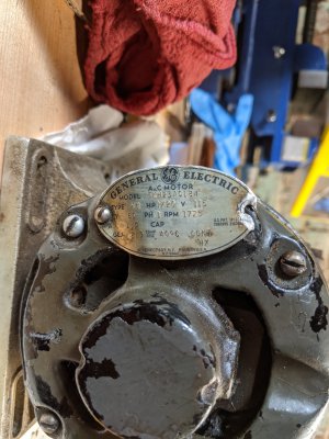
I have a GE single phase 1/20 HP motor. 5KH23AC184. It has a right angle reduction on it. Ohmed it out and wrote down the results.
T1 and T3 are one winding and T2 + T4 is the other winding. Both measure about 12.5 ohms, although T1-T3 is slightly less at 12.3 ohms.
The windings are isolated from each other and the case.

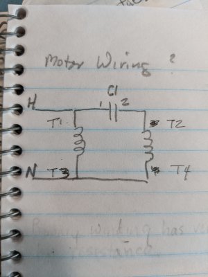
Tried wiring it up as following.

C1 is 1.5uF 450V. Maybe have misinterpreted the name plate. It looks like it is 1.5A, not 1.5uF. The value on the plate is blank.
Originally, when I opened the lube fill port for the gear reduction there was some congealed lubricant - more like grease really. No liquid lubricant. I filled it with gear oil. I think this unit hadn't seen lube in 70 years...
The motor hums but does not turn. There is no external motor shaft for me to give it a kick start. I unplugged it after 5 seconds. Nothing was warm, there was no smoke. Did I wire this correctly? Is my value for C1 wrong?
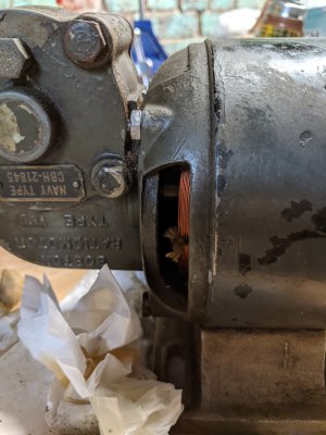
Removed the "brush" end off the motor to inspect it. With the back end off, the shaft turns freely and the gear reduction turns. I was worried about the reduction gearing, but it seems to turn ok.
Anyone got an idea on how to get this motor to run? Can't seem to find any info on this motor.
T1 and T3 are one winding and T2 + T4 is the other winding. Both measure about 12.5 ohms, although T1-T3 is slightly less at 12.3 ohms.
The windings are isolated from each other and the case.

Tried wiring it up as following.

C1 is 1.5uF 450V. Maybe have misinterpreted the name plate. It looks like it is 1.5A, not 1.5uF. The value on the plate is blank.
Originally, when I opened the lube fill port for the gear reduction there was some congealed lubricant - more like grease really. No liquid lubricant. I filled it with gear oil. I think this unit hadn't seen lube in 70 years...
The motor hums but does not turn. There is no external motor shaft for me to give it a kick start. I unplugged it after 5 seconds. Nothing was warm, there was no smoke. Did I wire this correctly? Is my value for C1 wrong?
Removed the "brush" end off the motor to inspect it. With the back end off, the shaft turns freely and the gear reduction turns. I was worried about the reduction gearing, but it seems to turn ok.
Anyone got an idea on how to get this motor to run? Can't seem to find any info on this motor.


