One last Modification on the GO727

iron man

Active User
Registered
Joined
Feb 7, 2013
Messages
792
100_0414.JPG


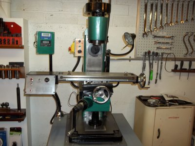
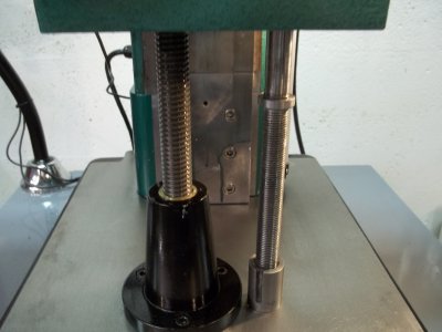
As you can tell from this picture the manufacture thought they would save a few bucks and mount the lead screw off center both ways. This probably would not be a big deal except when the gibs are tight to where the machine is usable the table twist both directions and shudders as you crank the table up or down. It drives the DRO nuts and is hard to come into something blind without breaking a cutter it would act like the table lock was tight. I had some time and I found an extra base incase my idea did not pan out so I thought I could make it better.

- - - Updated - - -
100_0489.JPG

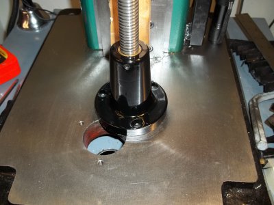
To start with I made a new lead screw nut base this one is made without a centering shoulder it is not needed I did not have any cast iron so it is made out of steel where it is setting is centered with the table. I checked my theory with a small jack and the table went up and down nicely no jitter.

- - - Updated - - -
100_0492.JPG


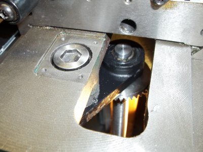
After some careful measuring I came up with a 1 1/2 x 1/2 steel bar stock and welded a piece of tubing to one end I then machined the whole unit so it was true and machined it for two bearings something it never had. the alan head bolt is something I made up and that is the original spot the lift scew come through it is now 2 inches back and 1 inch or so to the side.

- - - Updated - - -
100_0493.JPG

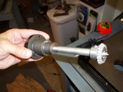
I then machined a aluminum shaft with a point on it for the crank screw and for the bearing block so I could perfectly aligh both shafts so both gears could mesh perfectly.

- - - Updated - - -
100_0494.JPG


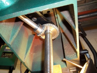
You can see from this photo the bearing block in place and the crank gear meshing with the main.

- - - Updated - - -
100_0496.JPG

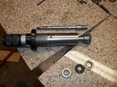
As you can see in this picture I made a longer shaft out of stress proof and I made a longer bear support to fit the original bearing support. There was no bearings in this unit except for a couple of thrust bearings shown in the photo. I used ball bearings at each end the front bearing is a Ford alternator bearing it was 10 x 27mm it pressed right into the stock housing the rear was a standard 10 x 28.
100_0414.JPG 100_0489.JPG 100_0492.JPG 100_0493.JPG 100_0494.JPG 100_0496.JPG
 
Last edited:
100_0497.JPG

I used a stainless plate to cover the old hole I wish I had a different base so I would not have to do that but for now it works maybe someday I will pull the base off and counter sink the plate into the base. It made a world of differance the table runs up and down without a jitter the DRO is much happier and really works well now. So lets re-cap on what has been done to the mill since I got it a year ago. First the home built power feed then the column extension with a larger acme scew then the DRO's after that the different crank handles including the one I made for the lift. Then I built a horzontal motor and spindle so I did not have to remove it from the top and put it to the side. And finally the changed position of the lift screw. This is what Sieg should have done in the first place when they built the machine they would have knocked it out of the park with just a few more inches of cast iron. So there I am happy now it is a nice solid mill a little bit americanized. Each mod is reversable except for the base and I have an extra one of those. Ray

100_0497.JPG
 
Last edited:
Good question I suppose a shorter path to the main lift screw would save money they would have to re-design the table, base and lead screw handle..It was not only off to one side it was way to far forward over 3/4 of the way forward that seem to hurt it more than anything. I had the time on the weekends and everytime I used it I got tired of making excuses for it so one night I took it all apart and looked to see what I could do. There was room under the cross feed screw so I just started in and it did not take long the bearings in everything makes a world of differance as well you can crank it up with one finger and the gibs are tight.. thanks for looking. Ray
 
Last edited:
The modifications you have made are fantastic, its amazing that you would have to go to such great extent but it looks like you ended up with a great mill. One thing I don't understand is why they would place the lift screw off to one side to start with? How would that have saved them money? You would think the designer would know that the table would be canted to one side when it was lifted?

Shawn

Never seen one off center before. Makes one wonder what the design team was thinking. Nice job
 
I use to run and old millrite that was off center because of the crossfeed screw but it was at least centered the other way. This one was off just about equally both ways. Ray
 
View attachment 59674


As you can tell from this picture the manufacture thought they would save a few bucks and mount the lead screw off center both ways. This probably would not be a big deal except when the gibs are tight to where the machine is usable the table twist both directions and shudders as you crank the table up or down. It drives the DRO nuts and is hard to come into something blind without breaking a cutter it would act like the table lock was tight. I had some time and I found an extra base incase my idea did not pan out so I thought I could make it better.

- - - Updated - - -

View attachment 59675

To start with I made a new lead screw nut base this one is made without a centering shoulder it is not needed I did not have any cast iron so it is made out of steel where it is setting is centered with the table. I checked my theory with a small jack and the table went up and down nicely no jitter.

- - - Updated - - -

View attachment 59676


After some careful measuring I came up with a 1 1/2 x 1/2 steel bar stock and welded a piece of tubing to one end I then machined the whole unit so it was true and machined it for two bearings something it never had. the alan head bolt is something I made up and that is the original spot the lift scew come through it is now 2 inches back and 1 inch or so to the side.

- - - Updated - - -

View attachment 59677

I then machined a aluminum shaft with a point on it for the crank screw and for the bearing block so I could perfectly aligh both shafts so both gears could mesh perfectly.

- - - Updated - - -

View attachment 59678


You can see from this photo the bearing block in place and the crank gear meshing with the main.

- - - Updated - - -

View attachment 59679

As you can see in this picture I made a longer shaft out of stress proof and I made a longer bear support to fit the original bearing support. There was no bearings in this unit except for a couple of thrust bearings shown in the photo. I used ball bearings at each end the front bearing is a Ford alternator bearing it was 10 x 27mm it pressed right into the stock housing the rear was a standard 10 x 28.

Hi Ironman, I have been thinking of getting one of these machines. In your opinion would you say the machine is not very usable in its stock form without the mods you made to the machine? Thanks liqwrench
 
No I would not say that, I did a lot of projects on this machine before I modified it and I really liked how solid the machine was when I got it. If what you are doing is not to large then it would be fine in its stock configuration. It would be better than an Atlas as far as upper column stability but on the lift screw Atlas would have the edge. I just have a habit of seeing engineering flaws and wanting to correct them and I push machines to there outer limits and try to make them act like there bigger counter parts. The nice thing about this machine is it is easy to modify if you choose and for under $900 you get a lot of machine and Grizzly is great if you do run into problems. I would still buy another if something happened to this one..Ray
 
100_0499.JPG

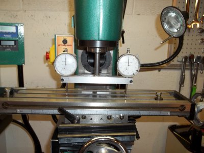
OK I said I would not modify the mill anymore but I did not say anything about tooling I made the tramming tool this morning it did not take long and I was surprised as to how well it worked. Ray

100_0499.JPG
 
Hi Ironman, thanks very much for the reply. I would like to say you did a great job on the machine. I do mostly small jobs and I would like to have a small machine because of limited space. I like the fact that this machine is both vertical and horizontal. I currently have a Smithy 1340 machine and it has limitations, it is usable but I want something more ridged. I think I will be getting this machine. Did you consider getting a second factory motor setup instead of building one from scratch? Thanks liqwrench.
 
100_0478.JPG
Hi Ironman, thanks very much for the reply. I would like to say you did a great job on the machine. I do mostly small jobs and I would like to have a small machine because of limited space. I like the fact that this machine is both vertical and horizontal. I currently have a Smithy 1340 machine and it has limitations, it is usable but I want something more ridged. I think I will be getting this machine. Did you consider getting a second factory motor setup instead of building one from scratch? Thanks liqwrench.

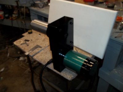
I am going to admit something I am cheap I hate buying anything when I can build it and sometimes better. The motor I used for the horizontal part was more powerful slower with more torque it was an american made motor and better yet it was free. By keeping neat stuff through the years I was able to build it for practically nothing. Ray

100_0478.JPG
 
Back
Top