- Joined
- Jun 15, 2018
- Messages
- 294
A lot of my (future) projects will be needing gears. Making gears with milling machine and indexing head would of course be quite easy. Since I do not have a milling machine not to taslk about an indexing device I need to look for another solution. Buying a milling machine would probably be the best but that thing needs a place to sit on. At the moment I am a little bit out of space in my shop so that is not an option. Also, the negotiations with my financial advisor would be quite something.
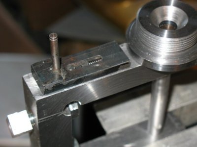
I ended up in creating a device that can be used to mill gears in a lathe. I got the idea from looking a video made by Rob aka Xyundu. This was one of the reasons I bought the vertical slide. Rob's design is looking really temporary but it served as a source of the idea. So I decided to make mine a little bit more like a tool.
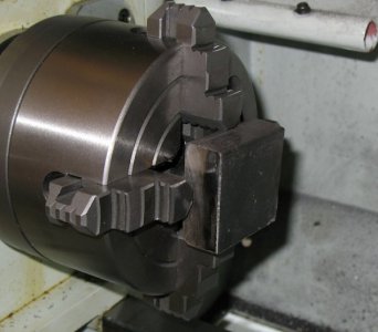
Starting with a mild steel block 100 x 100 x 20 mm.
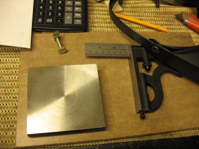
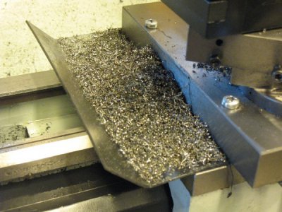
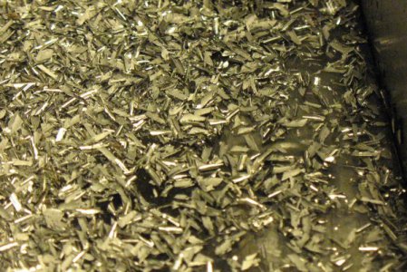
After doing the basic layout and boring some of the needed holes while the block was still intact I started the process of making a gap in the middle of the block. I do not own a bandsaw so my options are either a jigsaw or a hacksaw. Ended up using both. The jigsaw was used to make room for the hacksaw blade on the last cut. I have done a lot of cutting with hacksaw and I have learned diverse methods to get the cut straight. Without proper setup the saw tends to wander everywhere and occasionally also in the desired direction.
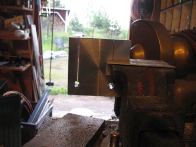
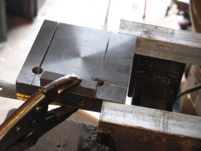
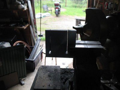
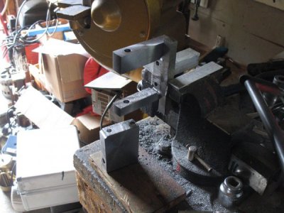
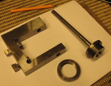
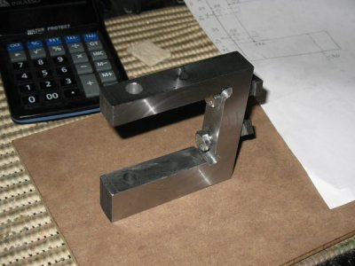
After a decent workout I now have a gap in the block. The surface finish is horrible. Well, I've got a bunch of good quality files. I also enjoy filing as there is something pleasant in getting really smooth finish on a lump of steel. It is like having a portable milling machine. I am quite satisfied with the result. It took me 3 hours to finish and I enjoyed every minute of it.
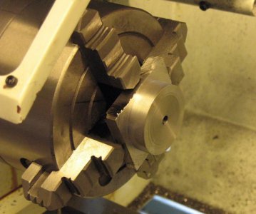
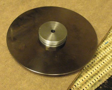
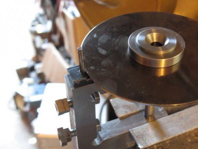
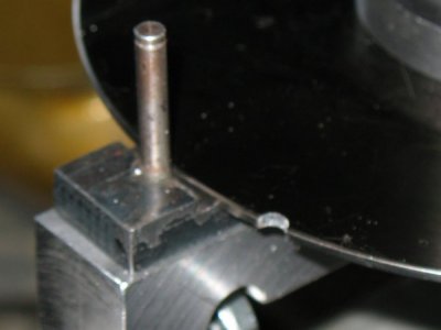
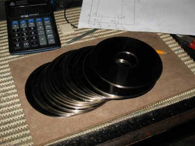
Rob used a cardboard wheel in order to index the gear. I will use a more permanent method. As I am an IT-Dinosaur I have collected some IT-Junk during all these years. I have a few aluminum alloy disks which are perfectly round, 3 mm thick and about 150mm in diameter. I will convert these into indexing disks and have a proper setup in the gear grider. Indexing the indexing disks involves some CAD work.
I ended up in creating a device that can be used to mill gears in a lathe. I got the idea from looking a video made by Rob aka Xyundu. This was one of the reasons I bought the vertical slide. Rob's design is looking really temporary but it served as a source of the idea. So I decided to make mine a little bit more like a tool.
Starting with a mild steel block 100 x 100 x 20 mm.

After doing the basic layout and boring some of the needed holes while the block was still intact I started the process of making a gap in the middle of the block. I do not own a bandsaw so my options are either a jigsaw or a hacksaw. Ended up using both. The jigsaw was used to make room for the hacksaw blade on the last cut. I have done a lot of cutting with hacksaw and I have learned diverse methods to get the cut straight. Without proper setup the saw tends to wander everywhere and occasionally also in the desired direction.


After a decent workout I now have a gap in the block. The surface finish is horrible. Well, I've got a bunch of good quality files. I also enjoy filing as there is something pleasant in getting really smooth finish on a lump of steel. It is like having a portable milling machine. I am quite satisfied with the result. It took me 3 hours to finish and I enjoyed every minute of it.

Rob used a cardboard wheel in order to index the gear. I will use a more permanent method. As I am an IT-Dinosaur I have collected some IT-Junk during all these years. I have a few aluminum alloy disks which are perfectly round, 3 mm thick and about 150mm in diameter. I will convert these into indexing disks and have a proper setup in the gear grider. Indexing the indexing disks involves some CAD work.


