Order of Operations

tonydi

Registered
Registered
Joined
Jan 1, 2013
Messages
148
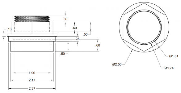
I'm going to be machining the part shown in the attached. It will be made out of one piece of 2.5"OD 6061 using my mini-mill and mini-lathe. I've been debating on the most efficient and least problematical way to machine this, which order to do each operation.

I've got to make four of these so my current thinking is to machine it from the "bottom up", and do everything up to the hex, flip it over in the chuck and do the rest with the exception of the hex, which I'll do last on the mill.

Am I just overthinking this or is there an argument for doing it in a different order?Nutv4.png
 
It's not overthinking; you need to think things through when starting a part. I think you are on the right track by machining from the bottom up, flipping the part in the chuck where you have a nice surface to grab, and finishing the part to include threads. Then you can cut your hex.

Are you making parts for the Sloan Valve Co.?
 
Couple thoughts. I am not sure I follow the whole drawing with what appears to be a bore after the threads the same diameter? That aside, how concentric do both ends need to be. Are you using a 4 jaw when flipping or is 3 jaw close enough? Also if you are using an index head in the mill be sure you have an end mill that can reach. For me my index head Chuck is large diameter and I would need several inches out of the Chuck for spindle clearance to cut the hex. Having what looks like .650” out to the end of the hex would be tough for me. I would machine the top end, thread bore step etc. complete. Then put in the mill and cut the hex. Then cut it off in a band saw or put back in lathe and part. Then turn. Grab to hex and machine the bottom side. If needed I would grab the hex in a 4 jaw and dial in on the small shoulder behind the hex. I may be missing something from the drawing but that would be my initial thought.
 
Your drawing doesn't make sense. There appears to be a counterbore under the threads that will remove all the threads. It's the top .50 dimension on your drawing.

Unless it’s a threaded hole and the exposed thread is a threaded adapter… you are right this doesn’t make sense. Plus threading up to a shoulder is very problematic.

Otherwise your bottom up approach seems sound.


Sent from my iPhone using Tapatalk
 
Heh, yeah, might have been helpful to actually say what the part is!

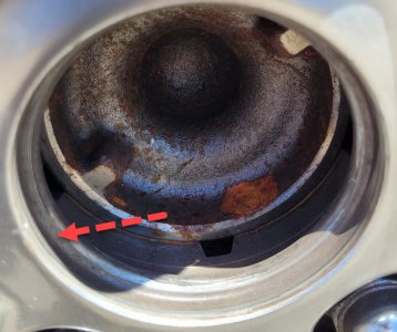
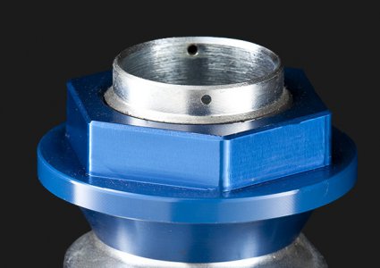
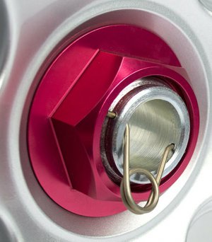
It's a replacement for the center cap on my wheels, meant to simulate a real center lock hub/nut assembly. Something like this...

nut.jpg

The "threads" are just fake and I cobbled together the drawing with just the threads offset to the outside of that top protrusion. It's still all just one solid piece of aluminum.

Tolerances? +/- anything I feel like except for the 2.37 diameter, that one needs to be probably within .010" because it has to fit down in a recess but not be too small.

wheel.jpg
 
Ok so based on that if the bore goes right through, or even if a partial bore then I would go with top side, hex then back side as I outlined above. That will make sure you have a full shaft to hold in the mill set up for the hex then turn and hold the hex in a 3 jaw and finish the back. As vtcnc mentioned though, that is a tight thread up to the shoulder. For the look you want a relief won’t work? That will be tricky. Have to turn slow and wind out fast while disengaging the half nuts. At least thread size is not critical so just go until it looks good.
 
As vtcnc mentioned though, that is a tight thread up to the shoulder. For the look you want a relief won’t work? That will be tricky. Have to turn slow and wind out fast while disengaging the half nuts. At least thread size is not critical so just go until it looks good.

I wanted the thread to appear to continue past the top of the hex because that's how it is on many real center lock hubs. I was going to chamfer the hex where it meets the thread to make it look like they are separate pieces. But this is all just rattling around in my head and I wanted to get the basic part done, maybe leaving thread for last. That's because it's hard to visualize just how the proportions of this whole thing need to be. It might be too big or comically small, won't know till I make one and slap it in there.

The thread thing may not even be necessary as some real setups have the end of the hub as a pilot and no visible threads. Obviously that would be a lot easier for me.

1.jpg2.jpg
 
Makes sense. Saving the thread for last and seeing how it comes together sounds like a good strategy. Can’t wait to see it. Fun project for sure.
 
Last edited:
Back
Top