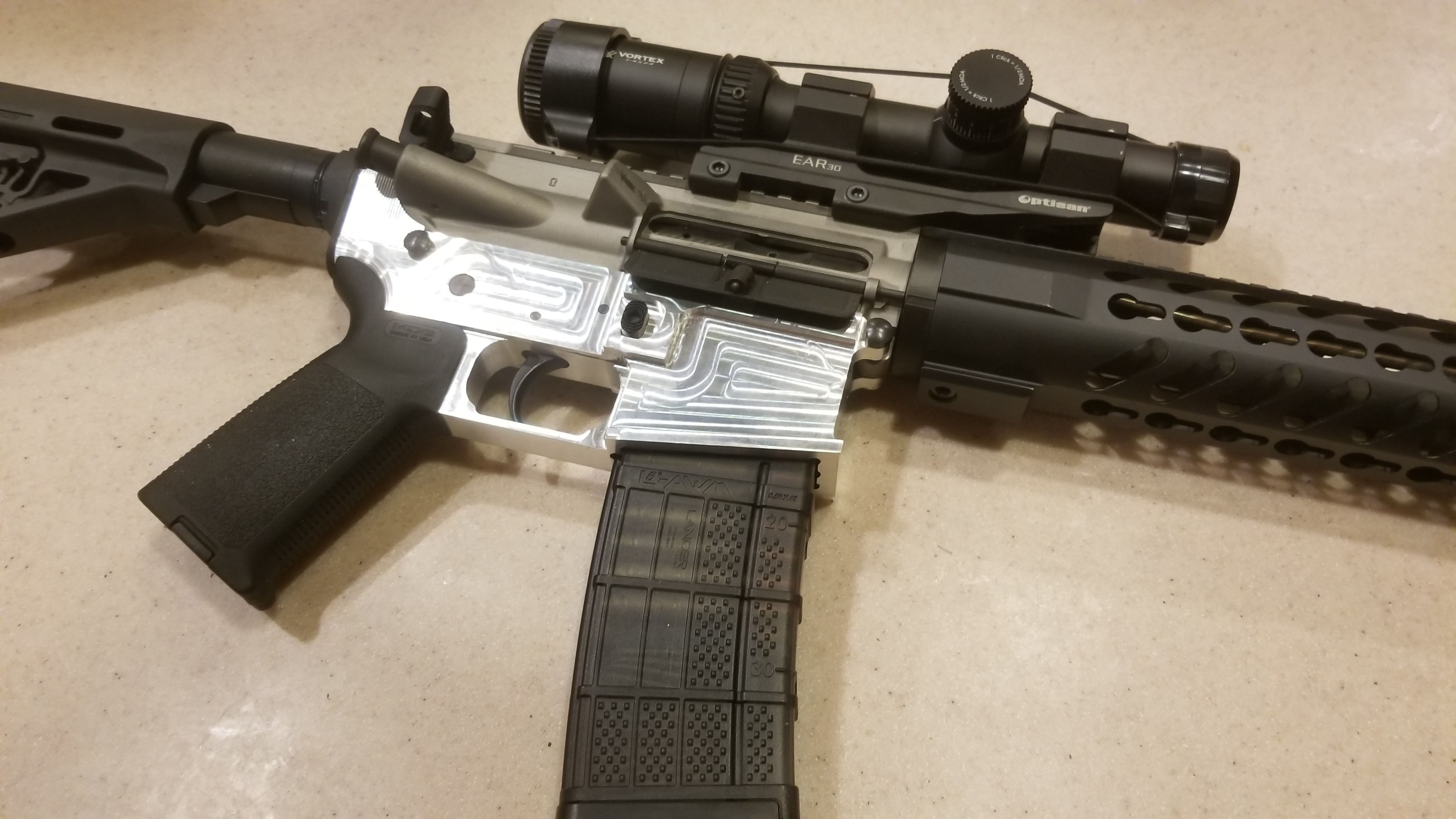
A friend who has made a couple of AR15 rifles from 80% lowers encouraged me to give it try since I have a milling machine - PM-25MV. I decided that since I would not be using the drill press/router method that he uses, I would first buy some stock and make some practice cuts, rather than destroy a lower receiver. I've done 6 practice cuts so far and they all suck. I learned some things along the way and things were improving and I expected number 6 to be great but it wasn't.
First I blue the stock and use a height gauge to make layout lines for a guide. I have made sketches with all the dimensions on how far I need to move the part. I have double checked the math and it works. My mill has a DRO. I also am using a brand new American made 2-flute 7/16 carbide end mill with AITIN coating.
I make a long cut downtime center of the part to a depth of 1.248" and is 2.562" long. This takes a while since no cut is more than .025". Once the cut reaches .630" in depth the length of the cut is shorter by .491". Each dimension that I work with is written on my vise so that I can always refer to it if necessary. When the dimensions change I remove to old ones and write down the new ones.
Once the centerline cut reaches 1.248" deep, I need to move on the Y axis .126" each way from center to make the width of the slot .690".
Every time I do this my finished parts do not measure out.
The width of my slot should be .690" but routinely measures about .683"
For the depth, which should be 1.248". When I took it out of the machine I looked at the readout and it said 1.249". Something I could live with. However, using a caliper I measured the depth and and it was reading about 1.265". Perplexed I put the part back into the machine and zeroed out the z axis on the top of the part then put the cutter on the bottom of the slot and the machine showed that it was 1.270". Now I had just taken this out of that same machine and the reading said 1.249".
The short cut that is .491" long should be at a depth of .630" but it was about .650".
The long dimensions, like the 2.562" length is fine. But depth and width dimensions are off.
The head is locked, and each axis is locked, as needed. So much so that once I make a cut for length and return to the zero position, I lock the x axis again - over and over and over.
I'm beginning to think that the fine adjust mechanism for the z axis is bad, but that wouldn't account for the y axis dimension errors.
Any ideas? Am I doing something wrong?
Thanks for the help.
Denny


