-
Welcome back Guest! Did you know you can mentor other members here at H-M? If not, please check out our Relaunch of Hobby Machinist Mentoring Program!
You are using an out of date browser. It may not display this or other websites correctly.
You should upgrade or use an alternative browser.
You should upgrade or use an alternative browser.
Please publish your ROTARY PHASE CONVERTER PLANS
- Thread starter HMF
- Start date
- Joined
- Jan 23, 2011
- Messages
- 246
This is just the info I need .I got a R P C that is home made and it works great but there is one thing I don't like . You have to turn on the main power then throw a toggle switch to make the start capacitors work then after the motor starts you have to throw it back.I have found on line instructions on how to make a automatic switch to start the motor.I would like some more info on how to build this. Has anyone done this . Thanks
- Joined
- Nov 28, 2010
- Messages
- 466
This is the wiring diagram I used when I built my RPC. I used a 3Hp, 3 Ph motor to run my 3 Hp milling machine. So far everything is working fine. I picked out a potential relay that has a continous voltage higher than what will be on the RPC so that I don't burn out the relay coil, and a drop out voltage of a little less than my line voltage so that the relay will open. I adjusted the capacitor size to give me the best operating amperage. The capacitor selection was just trial and error. Well, I guess the relay selection was too, if you want to get technical. The only changes I made to the diagram was to pull the voltage for the 2 run capacitors from different legs of power instead of the same leg as illustrated in the diagram, and instead of a toggle switch, I used a push button station so that I have to restart the RPC manually in case of power failure. If I lose power to the shop, the RPC will not automatically come back on when the power is restored. Just a safety feature.
http://www.wnysupply.com/index.cfm/fa/categories.main/parentcat/25431
Pat
http://www.wnysupply.com/index.cfm/fa/categories.main/parentcat/25431
Pat
- Joined
- Dec 30, 2011
- Messages
- 214

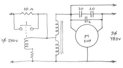
For what it's worth, this is my setup to get 480V 3 phase from a 240V 30A branch circuit, to feed my 550V Hardinge UM mill. The 10-ohm resistor limits the starting current and is shunted out of the circuit when the motor is up to speed. An autotransformer boosts the voltage from 240 to 480. The capacitor combination, effectively 16 µF, is a compromise between starting current and voltage balancing at no load and full load. They're what I happened to have: 20µF 600V GE SCR-commutating capacitors, and a 6µF 1500V.
The mill is rated at 3/4HP at high speed, 3/8HP at low, 550V but runs well enough for my purposes at 480V. The Bridgeport H head on the overarm has its own single-phase motor. The setup has been running for 15 years.

- Joined
- Dec 1, 2010
- Messages
- 1,172
I have put together several RPCs, I have long ago stopped using the cap start method. All the RPCs I do are pony start, and though I takes a few seconds to spin the motor up to speed, its more reliable than the offshore caps they sell here.
Allso have done them with tranformers to accomadate different machine voltages.
Pony start is simple, and I also never bother with trying to balance the legs. Providing the motor is at least 2 times the HP needed, its not ness. I will dig up a few pics if there is interest.
Allso have done them with tranformers to accomadate different machine voltages.
Pony start is simple, and I also never bother with trying to balance the legs. Providing the motor is at least 2 times the HP needed, its not ness. I will dig up a few pics if there is interest.

