PM-1640TL problems getting reasonable surface finish

Cermet inserts +all of the RPM's you have on the finish pass works pretty well, but it is okay to just accept the horrible finish and polish the crap out of it .. we all get the same results other than the rare cut in which it doesn't tear (using conventional tooling).
 
Try some CCGT inserts. Says they are for aluminum but they'll give you the best finish on steel too. Better finish that I've been able to achieve with HSS. My Precision Matthews turning set came with some and after having your same isssue, I gave them a try. They are the cheap variety you can find on Amazon, Ebay or AliExpress.
 
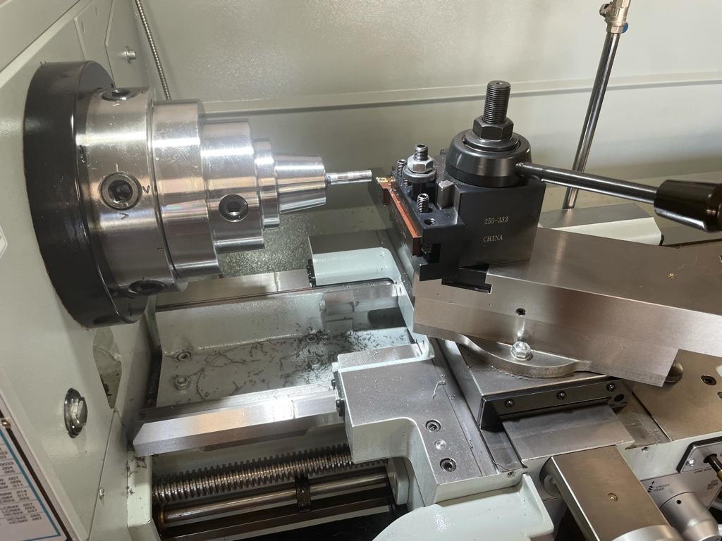
I’m having a problem getting good surface finish with my PM-1640TL. I don’t have enough experience to figure out what I’m doing wrong and am looking for ideas or to have my expectations reset. I am assuming based on seeing other PM-1640TL user videos on YouTube that it really should not be very hard to get great results over a wide range of speeds and feeds using carbide inserts and mild steel.

03df452253f04c67d475041dcab4cfff.jpg


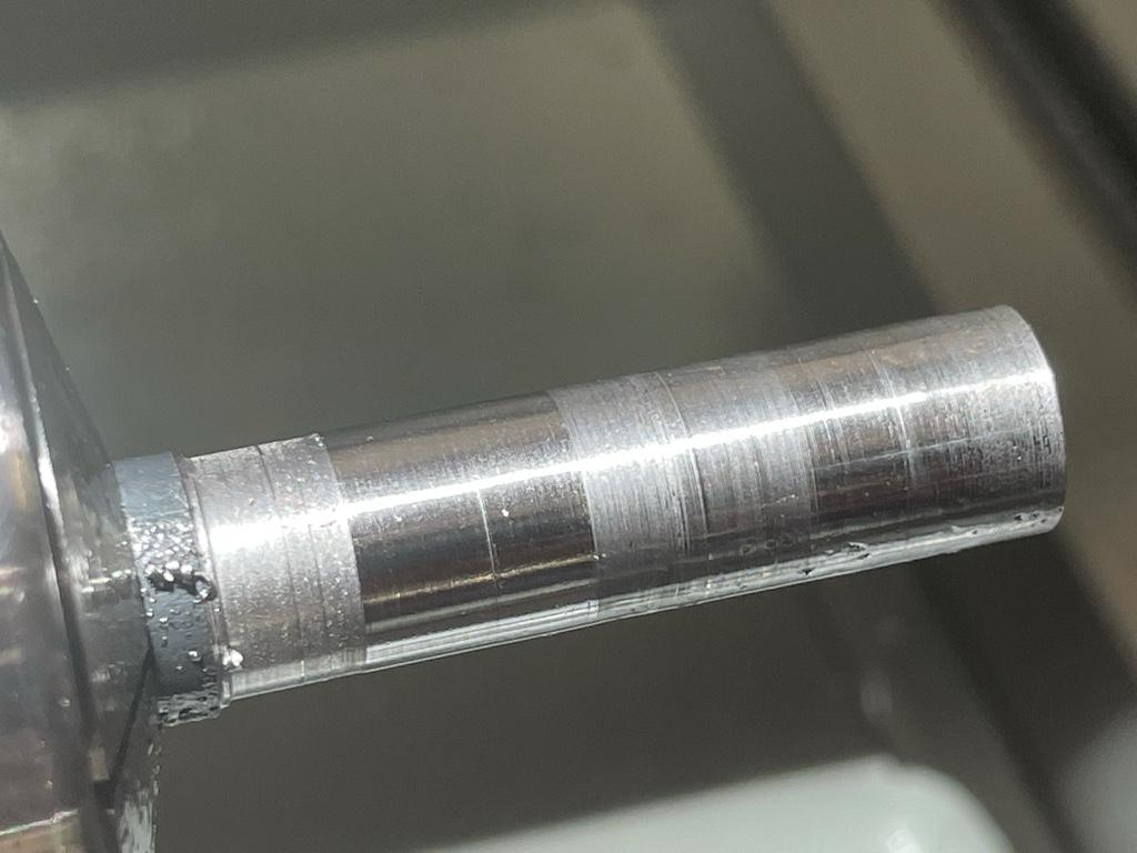
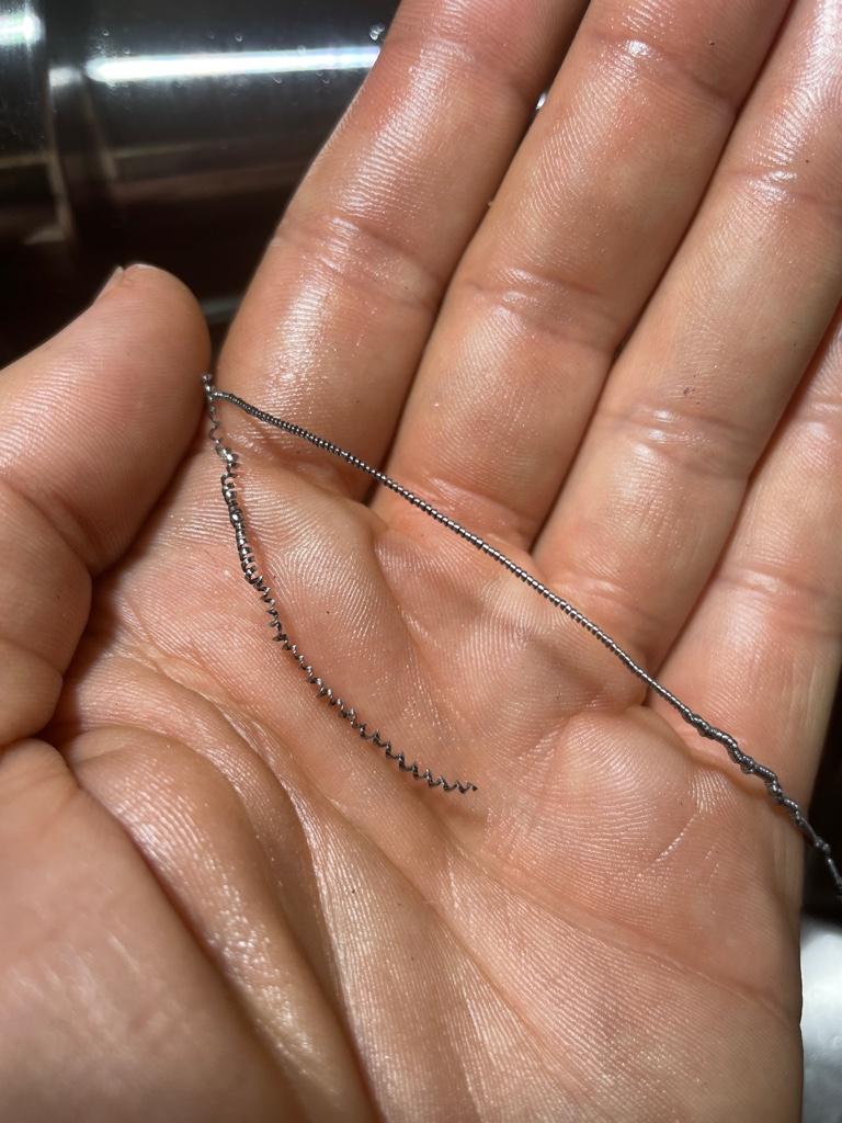
So, in detail, I’m trying to turn 1/2” mild steel with carbide inserts, and I always get some variation of the above picture, where there is inconsistent depth of cut. The chips vary somewhat with the speeds and feeds, but generally speaking are are super tight, regular and curly and bright. I am not really ever able to get them to break and be individual chips, which seems to be the issue maybe?

06c9ee76dde937c729f56585681f80b7.jpg


Things I have tried:

- Depth of cut from 0.001” to 0.040”
- 80 rpm to 1200 rpm
- Fine feed (0.004) through to coarse feed (0.22)
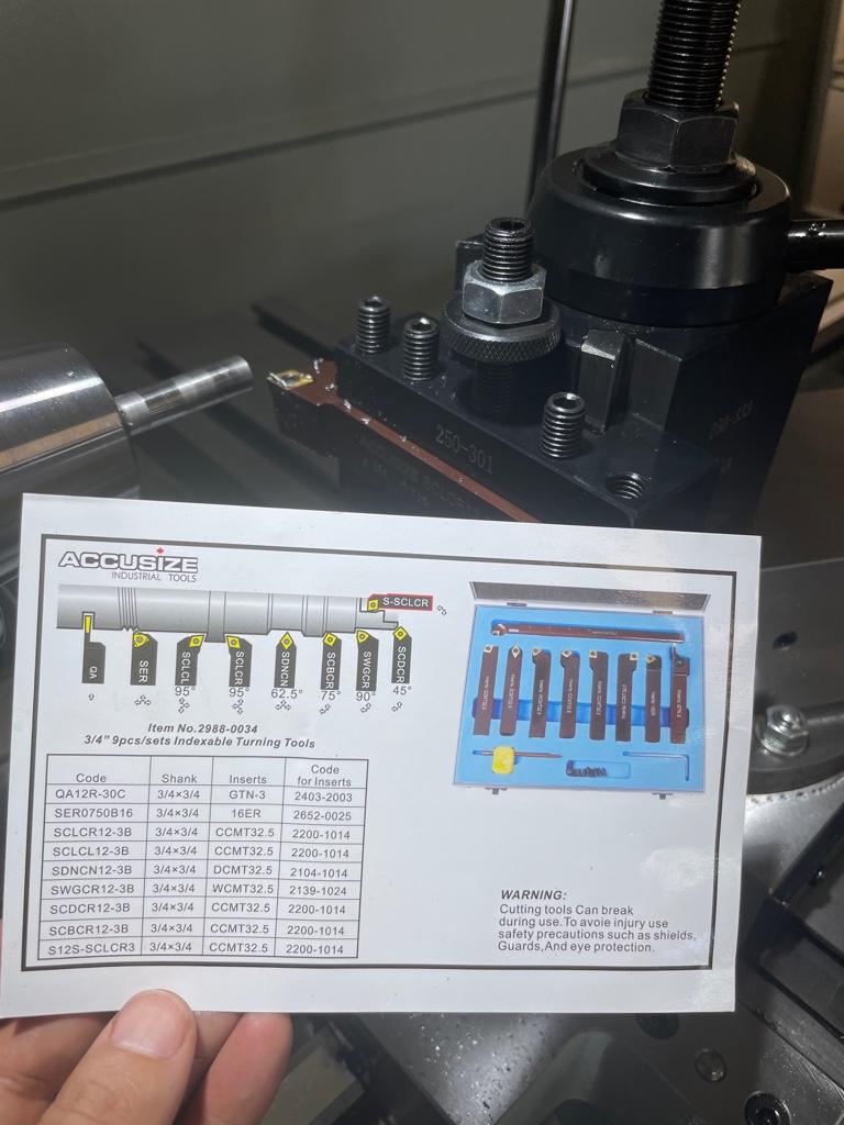
- Different carbide inserts and tool holders (right hand tool, and universal tool)
- High speed steel tool (pre-ground from the retailer and my own grind from blanks, sharp nose radius and large nose radius)
- 3 jaw vs collet chuck
- Tail support vs no tail support
- Two different sources of material
- Coolant vs no coolant
- Adjusting tool height from below center, to on center, to above center
- Tightening the v-belt tension
- Cross slide at 0, 45 and 90 degrees
- Making sure tool holder is square to chuck
- Making sure the tool post is tightened
- Making sure the chuck is tight
- Fixing the VFD frequency to 60hz (disabling the potentiometer speed control in the Hitachi VFD)

The depth of cut variation is like a thou or so. It’s more than just showing spiral tool marks, and it varies wildly.

The setup appears quite rigid and overkill to my (inexperienced) naked eye.

If I use emory paper to smooth down the result to debug it, it takes like 15 min with 340 grit and I am able to see during that process that some of the “banding” are quite deep grooves (and take forever to remove).

Ideas on what I’m doing wrong?

ef8b9e975d8aa0152cdffa9377804ce5.jpg


bbb0dfc8759196e0a46bfb2bf2c2b2fc.jpg
Same issue here. Glad you asked...glad you got all those helpful tips. I was getting awesome surface finish on Delrin (which was both good and frustrating given the mess I was making with some practice 1018). Love the collet chuck. How do you like it? Where did you get it?
 
Mild steel always tears like that in my experience, but carbide tooling can compound the problem.
Chrome-moly steels cut better, and steels with lead like 12L14
-M
 
Haven't read all the replies, but here are my thoughts to the original question:

1018 or most low carbon mild steels are hard to get a good surface finish. They tend to be gummy and tear out a bit. If you're not against leaded or sulphurized steels (better machinability), try 12L14 or 41L40. They cut like butter and give a much better surface finish. Harder alloy steels also give better finish, so try 4140. Bit more expensive but makes strong parts.

The general purpose inserts that ship with the import kits are poorly suited for fine machining. Either try so HSS, or better, experiment with different insert grades, edge preps, chipbreakers, and coatings to find ones best suited for your application. When finishing steels, I tend to use a CCGT32.50 (CCGT09T0304-AK) which is a razor sharp insert for non ferrous materials, but also gives outstanding finishes in steels, albeit with a reduced tool life. Here is an EXAMPLE. The general purpose inserts are pretty tough and are great for roughing, especially when your stock has a scale to it.

Even on a massive lathe, your thin workpiece is approaching or exceeding the 3:1 (length to diameter) extension rule for an unsupported workpiece. This suggests using a live center on a tailstock for added support when, say, you need to hold a 1/2" bar out more than 1.5". You'll find improved finishes and dimensional accuracy when supporting the work with a tailstock, even on seemingly short workpieces.

Inserts will NOT break chips unless you engage them enough (high enough depth of cut and feed per rev). The chip needs to be heavy enough to run into the chip breaking geometry on an insert. This also means you might be using different inserts for roughing vs finishing. Most quality inserts have a recommended SFM, depth of cut, and feed per rev which will get the insert working "properly". You can definity cut slower or lighter than these recommendations but it may not break chips. Also inserts made for brittle materials (cast iron) won't break chips on ductile materials (mild steel) due to the difference in chipbreakers. If you cut with a depth of cut less than ~75% of the nose radius of the insert, your radial cutting forces go up dramatically causing dimensional issues and poor finish. For example the CCMT32.50 insert has a 0.005" nose radius (fine finishing) so you should try to always keep your depth of cut greater than 0.004" (0.008" on diameter) or you could rub. The sharper inserts (CCGT) suffer from this less thanks to the sharp edge.

Here is an example working range for a CCMT09T0304-mm 2025 insert from Sandvik (high end). The shaded yellow region in the graph shows the recommended depth of cut (Ap) and feed per rev (Fn) in mm. In this case, you'd want the stay above approximately 0.8mm (0.031") depth of cut and 0.1mm (0.004") feed per rev. This is just an example and other insert manufacturers should have similar data available for each tool they make. Roughing inserts will have a higher minimum/maximum depth of cut, but will be stronger, and the opposite is true for finishing inserts.

1633535224719.png


In general, try to not sneak up on your final dimension. You'll find that taking a moderately deep finish pass will give you better finish and dimensional accuracy than skimming the last thousandth off the diameter. You'll have to characterize the deflection of the cut by taking similarly deep semi-finish passes and measuring in between.

Inserts are amazing when properly applied, so don't be discouraged that the freebie ones that came in the kit are giving you less than desirable results.

EDIT: Found a great picture from Sandvik showing the difference in DOC and feed for inserts made for roughing "PR", medium "PM", and finishing "PF". This was for some random insert family, but the nose radius, top rake, and land varied for each insert.
1633735292657.png


-Mike
 
Last edited:
Some of the deeper banding/grooves are likely built-up edge (BUE). This is where some of the workpiece material pressure welds itself to the cutting tool. This built up edge then does much of the cutting, effectively increasing the size of the tip of the cutting tool. Eventually it breaks off the tool and rolls under the edge allowing the carbide to start cutting again, until another BUE forms. This looks like rough grooves, ending in a "pill" or bump of material before the finish looks good again.

 
Last edited:
Some of the deeper banding/grooves are likely built-up edge (BUE). This is where some of the workpiece material pressure welds itself to the cutting tool. This built up edge then does much of the cutting, effectively increasing the size of the tip of the cutting tool. Eventually it breaks off the tool and rolls under the edge allowing the carbide to start cutting again, until another BUE forms. This looks like rough grooves, endinging in a "pill" or bump of material before the finish looks good again.

Thats an incredible representation. Thanks for posting that!
 
Thats an incredible representation. Thanks for posting that!
For sure! There a ton of older machining videos that are very informative. Also a whole series of these electron microscopy videos of single point cutting. Pretty awesome.
 
TNR Tool Nose Radius. Select a tool with a larger TNR it will be easier to get a better finish.
Also little passes are for finishing.
If you have .100 to remove to achieve your finished dimension then take two passes.
The pressure of a larger cut forces the "slack" out of the machine slides and makes the machine more rigid.
 
Back
Top