As
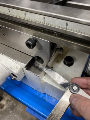
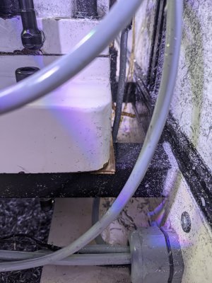
@Bluebutton and Matt at PM suggested, I completely loosened off the mounting bolts of the mill. While the mill was still secured to my stand, I took a feeler gauge under the saddle of the Y-axis and could fit a .009" shim under the back of the saddle. With all the mounting bolts loose I can fit a .002" shim under the rear of the saddle but only under the rearmost 3/4" of the saddle.
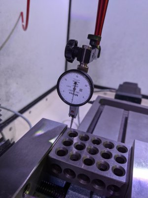
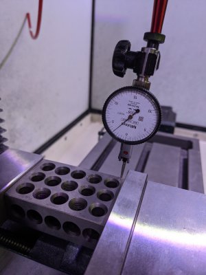
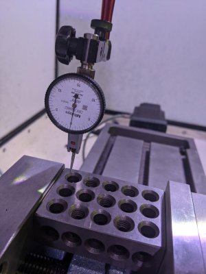
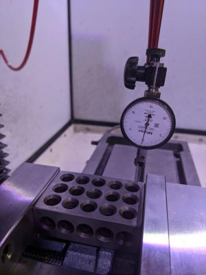
With all the mounting bolts loose and my vise trammed within .0003" in the x axis I'm seeing the y axis out by .003" over 3 inches now. It's not amazing, but it's better... The crazy thing is that the mounting bolts weren't even that tight.