- Joined
- Jun 25, 2020
- Messages
- 26
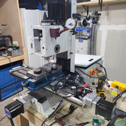
After years of watching this forum for ideas, last year i purchased a pm30 with every intention of CNC it from the start. So to document this headache im about to go on, i figured i would add to this site where i've gotten so many ideas from.
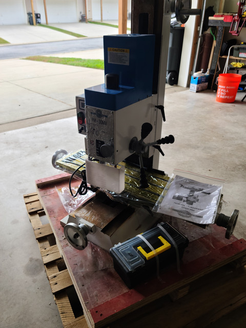
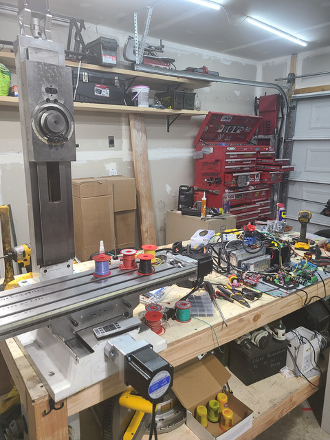
So it started off life back in October with this mill just sitting on the pallet longer than I wanted it too. life and work got in the way, so for the first few months of me having it, this is how it sat in my garage... sad and covered in the shipping oil..
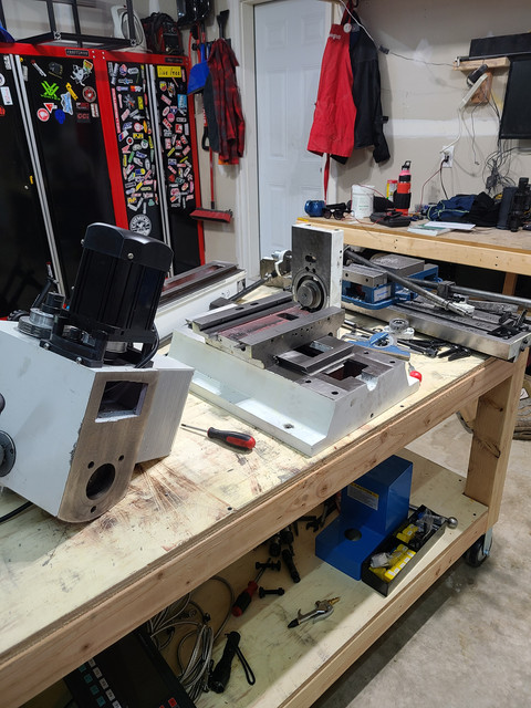
I went back and forward about if i wanted to make the kit myself or just buy one. Eventually i came to the point that if i dont buy one, i would never take it apart to get measurements and put it together to manually mill the parts. So finally last month i ordered a kid from dave so i went to town taking it all apart while waiting for it...
What seemed like forever, which was only 2 weeks, i had it at my door. When it arrived, well UPS had its way with it. i was missing the y axis and part of the X axis. but there was a Z in there. so that was a plus... And yes, that is part of the X axis sticking out.
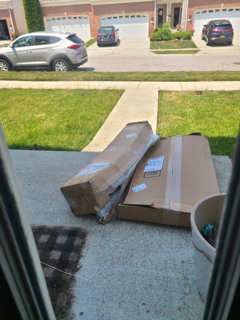
I will just like to add that dave is a stand up guy and remade all the missing parts and i had them in less than 2 weeks. Cant ask more than that. I hope he gets something out of UPS for this mess up.
Now one of the things i wanted to do is an epoxy/sand mixture in this. I've played with mills this size before and i know how much the can benefit from even adding 50lbs in there. So i went to at it making molds for this and filling it up.
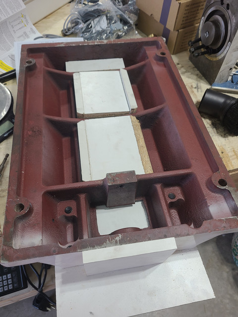
It was about 40 minutes after i filled the column is when i realized that i messed up and forgot to put release agent on the MDF in there... not sure what i was thinking as unlike the base, i need to remove it to get to the ballscrew in there. so i made the call to just pull it out the MDF pieces roughly half way through the cure time in there.
Liked i planned, the layers slid right out easily bending the small brad nails used to hold them in place.
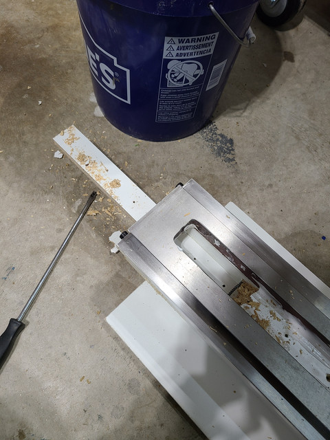
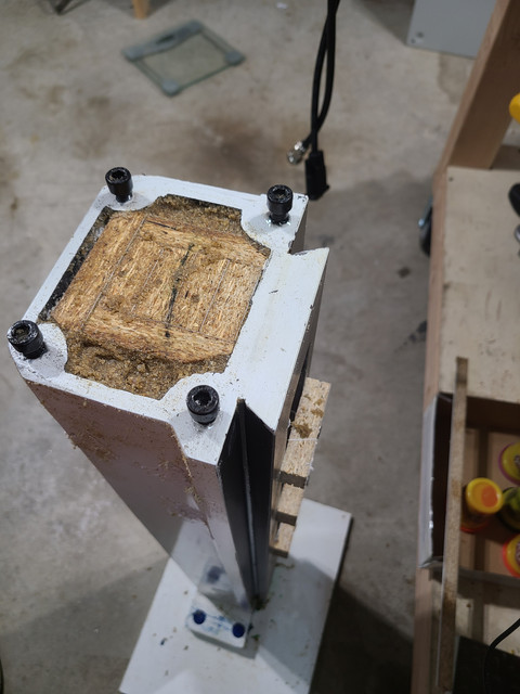
But the C channel i made that was in contact the epoxy... they took some persuasion.
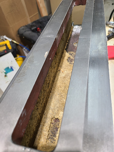
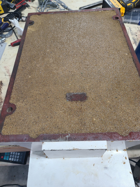
I knew that i was going to mess up the finish and probably put some marks in the fill from where i had screwdrivers and small prybars to break the MDF out, but getting it out was the priority. Overall it was worth it i feel. I added about 45lbs of mix to the base and 20ish to the column. I didnt fill the back of the column for the last 10 or so inches as i wanted access to the zerk so i could grease it up. While i only added 65lbs of epoxy granite to it, it just feels more dead and i think this will pay off in the long run.
There are plenty of other threads out there that would do a better job of documenting the assembly of this than i would ever do, so i will skip that part.
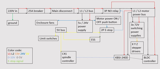
Now that the easy part is done, it was time to work on the electronics... i will be using mach 3 for now as am taking most of these parts off a router that i no longer use due to space issues in a 2 car garage. So an ESS will be the controller with a c26 on top. For spindle control, i have a c41 to change the PWM to an analog signal. I also will be using a kbsi 240 to convert the 0-10v to the 0-5V that the BLDC controller needs. Eventually this will get replaced with a marathon y551 i got for cheap on ebay. But need this running first to make the parts to mount the motor. Closed loop steppers on all axis will drive this as they are plenty for this hobby sized mill.
The mess begins...
still in bench testing mode, but everything fits in the enclosure... best part is when the vfd goes in, i can get rid of the KBSI and motor controller, so it will leave more room for activities. these activities include an extra driver for a rotary axis.
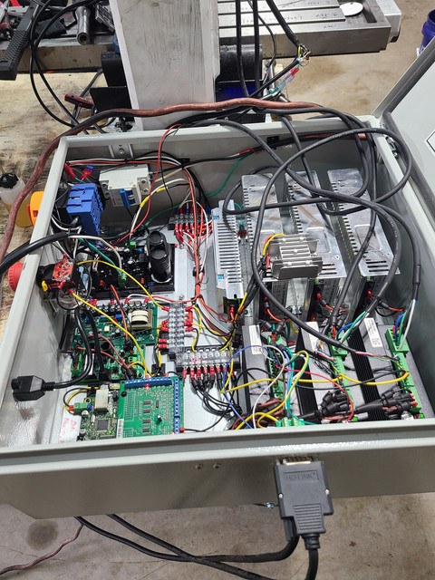
Still have a ways to go. Currently i have no limit switches. Need to make more holes to add the remaining axis motor connectors. one shot lube system will get done. NEED TO WELD A BASE AND ENCLSOSURE!!! and clean this wiring mess up.
But i am at a good start. unfortunately work will have me busy for another few weeks so this will be on hold until then. Hopefully this will encourage others to take the plunge into doing this. When i come back and post an update, i hope to show a base / enclosure for this and maybe start the motor swap.
So it started off life back in October with this mill just sitting on the pallet longer than I wanted it too. life and work got in the way, so for the first few months of me having it, this is how it sat in my garage... sad and covered in the shipping oil..
I went back and forward about if i wanted to make the kit myself or just buy one. Eventually i came to the point that if i dont buy one, i would never take it apart to get measurements and put it together to manually mill the parts. So finally last month i ordered a kid from dave so i went to town taking it all apart while waiting for it...
What seemed like forever, which was only 2 weeks, i had it at my door. When it arrived, well UPS had its way with it. i was missing the y axis and part of the X axis. but there was a Z in there. so that was a plus... And yes, that is part of the X axis sticking out.
I will just like to add that dave is a stand up guy and remade all the missing parts and i had them in less than 2 weeks. Cant ask more than that. I hope he gets something out of UPS for this mess up.
Now one of the things i wanted to do is an epoxy/sand mixture in this. I've played with mills this size before and i know how much the can benefit from even adding 50lbs in there. So i went to at it making molds for this and filling it up.
It was about 40 minutes after i filled the column is when i realized that i messed up and forgot to put release agent on the MDF in there... not sure what i was thinking as unlike the base, i need to remove it to get to the ballscrew in there. so i made the call to just pull it out the MDF pieces roughly half way through the cure time in there.
Liked i planned, the layers slid right out easily bending the small brad nails used to hold them in place.
But the C channel i made that was in contact the epoxy... they took some persuasion.
I knew that i was going to mess up the finish and probably put some marks in the fill from where i had screwdrivers and small prybars to break the MDF out, but getting it out was the priority. Overall it was worth it i feel. I added about 45lbs of mix to the base and 20ish to the column. I didnt fill the back of the column for the last 10 or so inches as i wanted access to the zerk so i could grease it up. While i only added 65lbs of epoxy granite to it, it just feels more dead and i think this will pay off in the long run.
There are plenty of other threads out there that would do a better job of documenting the assembly of this than i would ever do, so i will skip that part.
Now that the easy part is done, it was time to work on the electronics... i will be using mach 3 for now as am taking most of these parts off a router that i no longer use due to space issues in a 2 car garage. So an ESS will be the controller with a c26 on top. For spindle control, i have a c41 to change the PWM to an analog signal. I also will be using a kbsi 240 to convert the 0-10v to the 0-5V that the BLDC controller needs. Eventually this will get replaced with a marathon y551 i got for cheap on ebay. But need this running first to make the parts to mount the motor. Closed loop steppers on all axis will drive this as they are plenty for this hobby sized mill.
The mess begins...
still in bench testing mode, but everything fits in the enclosure... best part is when the vfd goes in, i can get rid of the KBSI and motor controller, so it will leave more room for activities. these activities include an extra driver for a rotary axis.
Still have a ways to go. Currently i have no limit switches. Need to make more holes to add the remaining axis motor connectors. one shot lube system will get done. NEED TO WELD A BASE AND ENCLSOSURE!!! and clean this wiring mess up.
But i am at a good start. unfortunately work will have me busy for another few weeks so this will be on hold until then. Hopefully this will encourage others to take the plunge into doing this. When i come back and post an update, i hope to show a base / enclosure for this and maybe start the motor swap.
Last edited: