- Joined
- Jan 10, 2019
- Messages
- 1,042
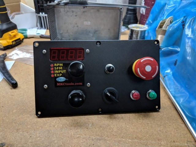
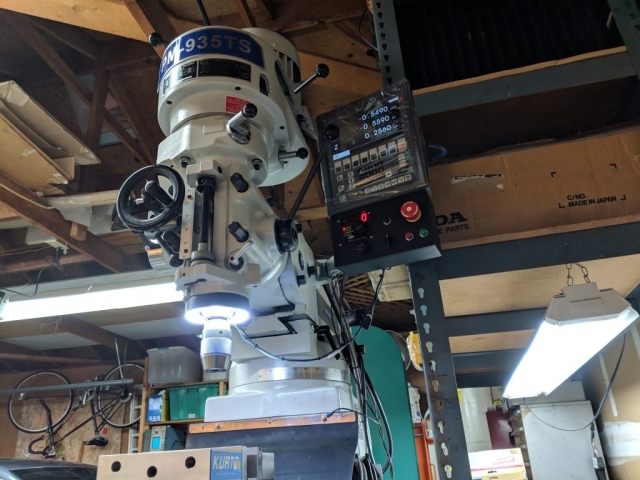
Having finally gotten everything up and running, I thought that I'd give back to the group. The following is how to configure the Hitachi WJ200 VFD to control a PM935 mill with its 3-phase motor. The following assumes that a remote speed pot, forward switch to terminal 1, reverse switch to terminal 2, and Jog to Terminal 3:
Disclaimer: These settings worked for me, but these are not all the settings in the VFD, so it doesn't get around having to learn the unit.
Configure start/stop switch inputs, pg 4-16
A002 = 01
Set Fwd to terminal “1”, C001 = 00
Set Rev to terminal “2”, C002 = 01
Configure remote speed pot, pg 4-28
Pot on terminals “H”, “O”, and “L”
A001 = 01
A005 = 02 (confirm) (“AT” defaults to off, so selects pot by default)
DC braking, pg 3-26
A051 – 01 (enable during Stop)
A052 – brake applied below this frequency
A053 – Wait time before braking
A054 – Braking power, 0-100%
A055 – Braking duration, shorten this some?
A059 – Carrier frequency during braking
AC Braking, pg 3-71
Connect resistor to terminals “+” and “RB”
B095 Dynamic braking control, 01 = enable during Run
B096 Activation level, 360
B090 Dynamic braking usage, % per 100-seconds, 0.0-100.0%
B130 Overvoltage Suppression = 1 (enabled)
Jogging, pg 3-21, 4-19
Set terminal input, C003 = 06
Frequency, A038, try 4.0 Hz
Jog deceleration, a039 = 2 (DC braking and stop)
Notes:
· A038 must be > B082, or the value is zero
· Press Jog, then Fwd or Rev
Carrier frequency, B083, pg 3-69
B083, increase to decrease whine. 5 – 12KHz (motor runs warmer), set to 10
B089, automatic carrier freq reduction (to a minimum of B083), set to 01
Unattended Start, pg 4-25
Set terminal input, C004 = 13. Wire input “4” permanently high
Stop/Restart Mode, pg 3-72
B091, 00 = controlled deceleration
B088, 02 = resume motor drive at current spin-down speed (active frequency matching)
If you decide to try the "auto tune" feature:
Auto tune, pg 3-104, 3-108.
Auto tune selection, H001 = 02 (enabled with motor rotation)
Motor constant selection, H002 = 02 (use auto tuned data)
Motor capacity, H003 =2.2
Poles, H004 = 4
Notes:
· DC braking must be disabled (A051 = 0)
· Simple positioning P012 = 0