- Joined
- Aug 7, 2020
- Messages
- 29
Aaahhhhh, you said 7 tooth crank... yeah, division by 7 takes a different approach. You can do the geometric layout with a compass and scribe using dividing techniques known since antiquity, and using a mill vise, v-block, and square you could mill the form "good enough" for a crank handle, yes? If you have the Karl Moltrecht books, the chapter on dividing is excellent.
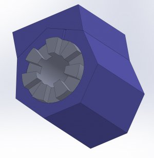
Maybe using Solidworks is cheating, maybe it won't work? But here's my tentative plan:
I will 3d-print the blue 7-sided collet and vise block in these pics. Then I will center on the part ID. Using a 1/4" end mill I'll offset my center by 1/8" along one axis. Then I will run the mill all the way through both sides of the round part. This will cut one edge of one tooth and the opposite edge of the opposing tooth. The rectangles imposed on the round part in the one pic will be my cuts. By rotating my block I'll just run the cut along the same axis again all the way through. After repeating this 7 times I should have all 14 cuts done accurately. I'll probably rubber cement the piece into the collet so that it doesn't rotate on accident when I am rotating the collet / it isn't in the vise. Anyone see any issues with this idea?
I'll probably also print a 6-sided collet so that I can flip it over and cut a hex on the other side for the socket.