POTD- PROJECT OF THE DAY: What Did You Make In Your Shop Today?

Thanks. It's been rubbed on a little. Bored, stroked, cross bolted mains, hyd roller cam, ported heads, etc., backed by a five speed Tremek. Should get down the road in a satisfactory manor. Mike
I would think you would need a lot of CFM’s to feed all that displacement

Especially at altitude
 
I generally only work on it when Evan comes up from Denver. They were here over Thanksgiving, so we got a bit more done. I'll finish up the valve train, as that's a bit beyond his current skill level. It will get finished, and back in the car this summer, as he has the summer off from his teaching job. The old engine had an 800cfm carb on it. May try to get some video with sound when it is finished.The engine isn't huge, just 434 c.i. (originallly a 360 truck block), and may be upgrading to a Sniper fuel injection setup. should be making in the neighborhood of 520-550hp, with similar torque numbers. I have some more interesting engines coming up, but no solid schedule, just get to them when time allows. Mike

I would think you would need a lot of CFM’s to feed all that displacement

Would have liked to hear that kitten purr. Looks stunning Mike.
 
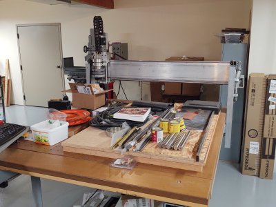
Working on the largest chunk I've ever put on a bridgeport table.

This is the gantry for a 4x8 CNC router that I'm building with some friends. The raw weldment is 60-1/2" long and somewhere around 120-130 lbs. Two 4x4x3/16" square tubes with a 2-1/2" gap between for the ballscrew. 1/4" thick end plates and 2" square tube spacers holding them together. 1" wide strips to support the linear rails are stitch welded on the front.

First step was to get it mounted on the table. We planned the design around this operation. The 2x2 spacer tubes are cross drilled 5/8" for clamping studs and the outer two are located so they line up with the bridgeport table slots. Since it is a weldment it is distorted. We're supporting it on three points so that it won't spring after we unclamp it. Dialed it in more-or-less parallel to the table since the final accuracy comes from the machining, not the original weldment.

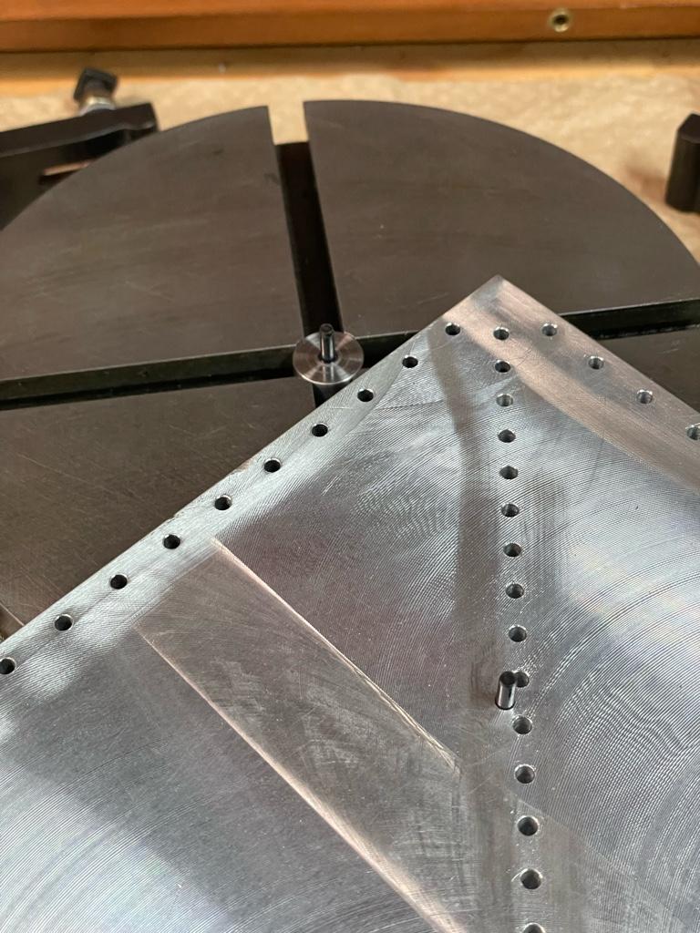
Drilled three 0.250 reference holes in the front face of the upper tube. One dead center, the others exactly 11" each way. We have to rotate the turret and extend the ram to reach the ends, but we can put a dowel pin in a collet and pick up at least one reference hole at any turret location so we can properly set the DRO.

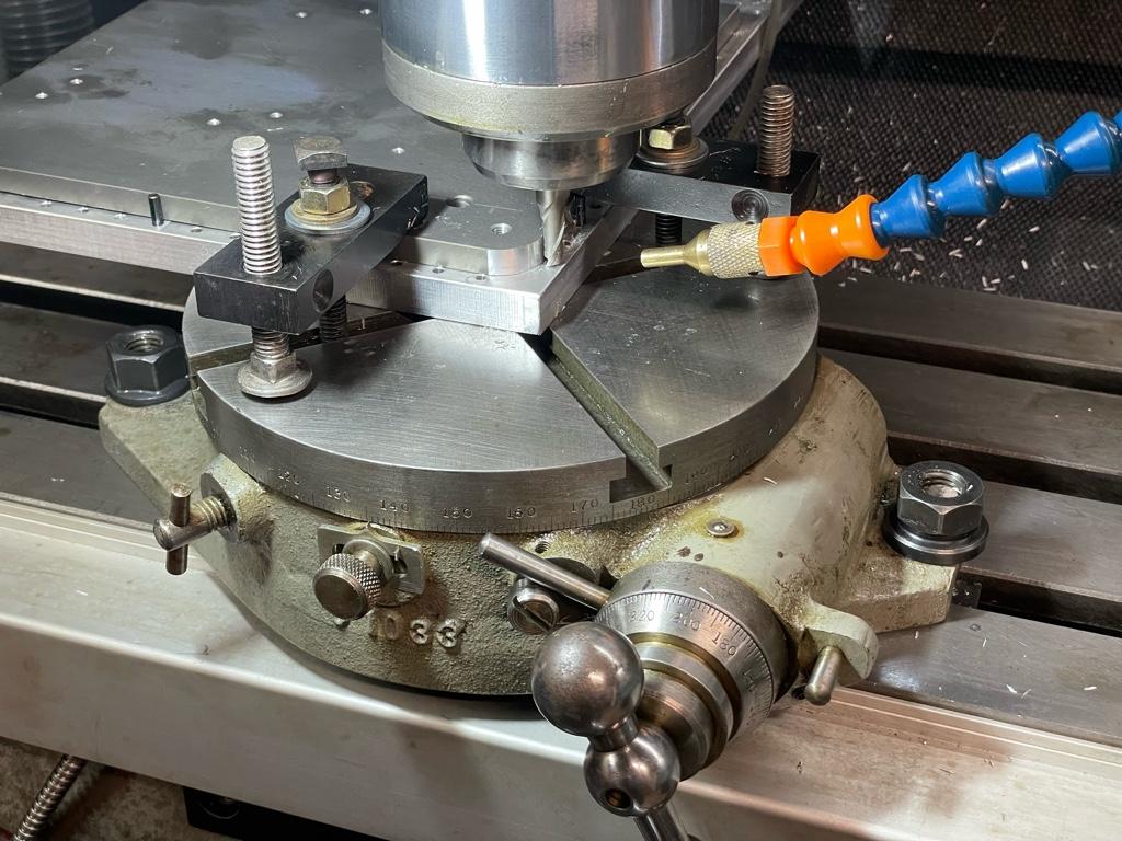
Pictured is milling the linear rail support strips. We did the middle section first, then rotated the turret to the left and finally to the right.

The upper strip started 1/4" thick and we milled off about 0.030 full width in the middle. Because the weldment is distorted it was closer to 0.070 at the ends, but the result is a flat front face. The lower strip started out 5/16" thick. It is milled flat to the other strip, so we took off about 0.090 in the middle and roughly 0.130 at the ends. Unlike the top strip we didn't mill all the way across, instead we left a shoulder on what will be the bottom edge. (See red arrow in the CAD screenshot.) That way when we mount the linear rail we can clamp it against the shoulder so it will be straight in that axis.

Next step will be drilling and tapping the 50 holes to mount the linear rails. Same setup on the bridgeport, again using the reference holes so we can continue the hole pattern accurately after moving the turret. We were hoping to do it all last night but the milling went slowly and it got late. We left everything set up for the drilling...

20221126_200321_003_01s.jpg20221126_200357s.jpg20221127-ss.jpg
 
Last edited:
130 lbs just for the gantry beam? Wow. Is this machine going to run in super slowmo? It must be a substantial machine, what are the specs?
 
130 lbs just for the gantry beam? Wow. Is this machine going to run in super slowmo? It must be a substantial machine, what are the specs?
It's intended to be a pro-grade heavy duty wood router, suitable for cutting things like cabinet sides, etc. With the goal of also being rigid enough to be able to cut aluminum. 2.2kW spindle motor, 4' x 8' table capacity. On a par with something like a Shopbot Alpha (https://www.shopbottools.com/products/alpha), Laguna Swift (https://lagunatools.com/cnc/swift-series/standard/), or Grizzly G0985 (https://www.grizzly.com/products/grizzly-4-x-8-cnc-router/g0895)
 
It's intended to be a pro-grade heavy duty wood router, suitable for cutting things like cabinet sides, etc. With the goal of also being rigid enough to be able to cut aluminum.

Naaah, You're building another workbench/storage unit.
Trust me, that's what they usually get used for. ;)
 

Attachments

  • StorageRounter.jpg
    StorageRounter.jpg
    448.4 KB · Views: 37
I tried making the Hemingway tailstock die holder. I watched a few vids and reverse engineered it. I need to make a 13/16” adapter and the Morse #2 shaft. It looks like it should work. Time will tell.
6ac69320428e741975fefdb726c010be.jpg


Cutting oil is my blood.
 
Back
Top