POTD- PROJECT OF THE DAY: What Did You Make In Your Shop Today?

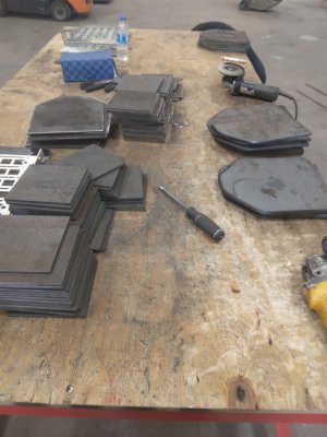
Not today, but I completely forgot to post this awhile back, and I really didn't know if I should at the time. Any way, my company got a contract for chest and backplates for the Ukraine. Don't remember the composition of the steel but it wasn't common, pretty proud of it at the time, even tho had to deal with some questionable characters. Shipped by air immediately,. Pretty cool. We contracted it on being able to use the lazer, but ran into problems with the material, but plasma worked just fine.
 

Attachments

  • 20220606_095844.jpg
    20220606_095844.jpg
    218.5 KB · Views: 58
Last edited:
3D printed a micrometer holder for my lathe.
That's an idea! I just finished repairing an old dial indicator that came in a lot of indicators. Now that it's working the plan was to make indicator holder for the toolpost. Never think of 3D printing, even though there's one sitting on the bench behind me as I type this!

But, the big question. Can someone tell me what the tip of this indicator was for? It's three flats ground to make a point. Never seen on like this before. My guess is to check countersinks or something, but not sure. The sharp edges don't match a flat head screw, so that's out. Someone ovbiously spend some time making this, based on the ground surface it was certainly intentional.

Anyway, this indicator now has a big button type end for lathe centering stuff...
 

Attachments

  • Indicator tip.jpg
    Indicator tip.jpg
    294.6 KB · Views: 28
That's an idea! I just finished repairing an old dial indicator that came in a lot of indicators. Now that it's working the plan was to make indicator holder for the toolpost. Never think of 3D printing, even though there's one sitting on the bench behind me as I type this!

But, the big question. Can someone tell me what the tip of this indicator was for? It's three flats ground to make a point. Never seen on like this before. My guess is to check countersinks or something, but not sure. The sharp edges don't match a flat head screw, so that's out. Someone ovbiously spend some time making this, based on the ground surface it was certainly intentional.

Anyway, this indicator now has a big button type end for lathe centering stuff...

Metric flat heads are commonly 90°. US flatheads are commonly 82° and sometimes 100°. Will the tip match any of those angles?

My guess was for checking countersinks or chamfers (at holes). You'd have to mount the DI in a frame of some sort (similar to a depth gage with legs). If you wanted a countersink that was effectively .200" deep, the DI would read .200 on a flat surface and read zero in the countersink.
Could be a shop-made modification; all of the countersink depth gauges I have seen have cones, and they're not cheap so fabricating one makes sense:

Starrett 687-3Z.png
 
Today i finally had some time to work on the shed, its been waiting for outer sheet metal for half a month now. It's december but the weather seams to forgotten its still green and warm. On the shed i still need to make the front door and cover the front. I have some free time coming and there are lots of holidays in january, i'll finish it then it seams. I did have to move back all the sand bags next to it and still doesn't look great but is better.
IMG_20221126_111357.jpgIMG_20221126_111342.jpg
 
My big Jet lathe should have a lead screw support, but it was missing when I got the lathe. I started in on making one.
max milling.jpg
max.jpg
This will be the top block that rides on the V way. Chewing out as much material as I can before I tilt the head 45 degrees.
 
Finally cobbled together a display mount for the TouchDRO tablet.....IMG_20221203_114629452.jpgIMG_20221203_114654104.jpg

The black arm is a TV mount arm obtained from Ebay. I just put the arm on a bit of plate to mount it on the mill, and fabricated the tablet holder.

Also made a lathe tool height setting gizmo, following examples seen on Tom Lipton's youtube and others here.IMG_20221203_120659403.jpgIMG_20221203_120751539.jpg

Threaded 1/2-40 for precise adjustability. There is a nylon tipped set screw fix the setting.

-Pete
 
The touch DRO is super cool looking but what it the advantage of the Bluetooth connection? You still have wires from the readers to the BT box, yes? Now you need 2 power supplies, one for the BT box and one for the display?
I am struggling on a DRO for my lathe. The other problem is I need slim scales at least for my cross slide. It is only 1" thick.
 
Pro’s: Flexible location of the display (Mini-Mill doesn’t lend itself to mounting a large display), cables from scales can be confined to the machine, can use lower cost scales (for Mini-Mills the iGaging SS Absolute Plus scales provide adequate resolution), fewer power cables than using individual readouts, you can use the tablet to access web-based resources and Yuriy - if you have issues or questions he actually gets back to you.

Cons: Separate power supply to the TouchDRO Box & tablet.
 
Back
Top