POTD- PROJECT OF THE DAY: What Did You Make In Your Shop Today?

@Shootymacshootface

What tool did you use to cut the wooden threads?
I would expect a solid blade to result in a lot of tear out. Your threads look good.
I used a razor sharp hss forming tool that I ground to match the threads on the broken off piece. The threads are 5tpi and they look like buttress threads. This was my second attempt at doing this. On first attempt, was taking .010 cuts, it tore the wood out instead of cutting. On the second attempt, I only took 2-3 thou at a time.
 
This is a new thread that I am starting. We want to know what you made in your shop today. No limits, just tell us what you did.
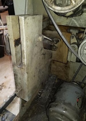
Today I figured out how to remove the quill from my JET JVM-626 mill. Someone who had it before me managed to force the quill down with the quill lock tightened. It put a 4" vertical scar about .009 into the body of the quill. I don't really know anything about machining or the mill, so I am being very careful about how I go about trying to repair. Anyway, the plan is to drop the quill, smooth the scar so it won't impede smooth movement in quill travel. Then I'm going to clean it, chase all the treads with a tap and replace all of the screw driver head, threaded fasteners with Allen heads. Then reassemble, check for run out and pray there isn't any.
 
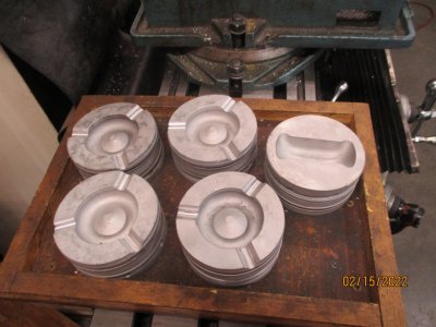
A neighbor gave me some used pistons from a 5.9 Cummins diesel engine and I turned them into ash trays, I gave one to my friend who smokes, and am hunting a good home for the rest.IMG_0010 (5).JPG
 
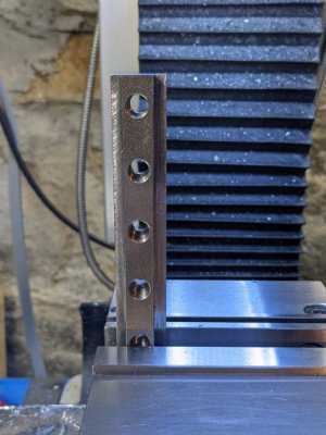
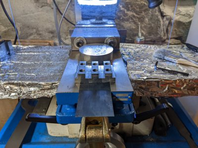
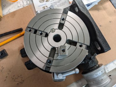
Made some tee-nuts for my new HV-6 rotary table. Kind of an odd size slot, 11 mm. Made 6 tee-nuts. 5 came out as planned. Kind of spaced out drilling the last hole. Hole is off by 1mm. The nut is asymmetric, but it is still serviceable. Think I will boil blue them. Never tried blueing that way. Have the peroxide, been wanting to try it.
PXL_20220216_002913381.jpgPXL_20220216_022841799.jpgPXL_20220216_023227379.jpg
 

Attachments

  • HV-6_Tee-Nuts.pdf
    202.8 KB · Views: 11
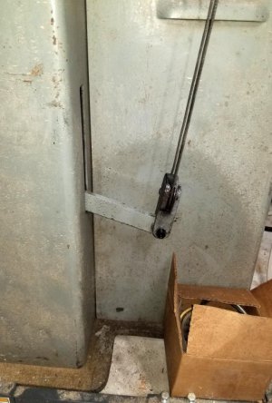
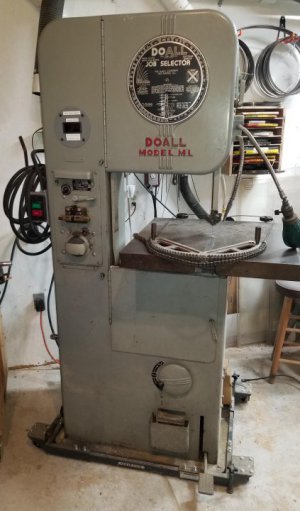
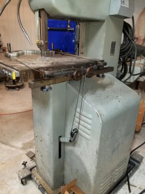
POTD was bolting a power feed cable/chain setup to my circa 1948 DoAll 16” bandsaw. Most DoAll’s don’t have the power feed on them for some reason. Might be it was an accessory and not included with the saw? Regardless, really “tough” job to run three 3/8” bolts through the mounting bracket into the back of the table and attach the bottom cable pulley to the actuator arm.


My DoAll 16" ML bandsaw
20220214_142944.jpg
Power feed installed. Pedal down position here. Releasing the pedal drops the feed weight and the actuator arm. Cable is pulled down taking the work holder with it.
20220214_142953.jpg


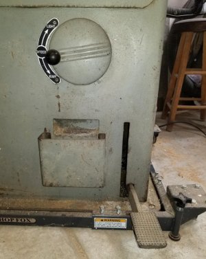
So why does this 3-bolt project warrant a post in the POTD string? I thought others may be interested in the “quaintness” of the power feed design. Quick version is it’s nothing fancy. The feed is powered by gravity via a weight inside the saw. Step down on the pedal at the base of the saw to lift the weight, position your work in the work holder, release the pedal and the cable/chain pull the work into the blade. The pressure can be varied by moving the weight along a pivot arm. This is done with the speed adjustment handle on the front of the saw. According to the manual, pressure varies between 25 – 80 lbs. You can also feather the weight with your foot on the pedal.


Step down on the power feed pedal to lift the weight. Move the pedal sideways to catch lock it in the "ready to go" position. Pressure is varied by the feed crank, 50 turns to go from 25 lbs. to 80 lbs.
20220214_143115.jpg

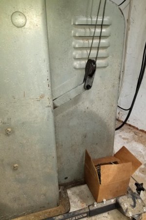
Actuating arm on the back of the saw in the "ready to go" and "deployed" positions. A length of braided cable goes through the pulley and up to pulleys on the mounting bracket.
20220214_143032.jpg20220214_143041.jpg


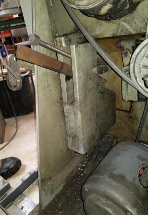
The actuator arm out of the back of the saw has a pulley with a cable. The cable runs up to a mounting bracket with a pair of fixed pulleys. There are two removable pulleys that mount to the mounting bracket, these are just above the table top. The cable runs through the removable pulleys and terminate with either a hook or roller chain.


Feed pressure crank on the front of the saw moves the feed weight along a parallel feed arm.
20220214_143238.jpg20220214_143425.jpg


I set up for a cut by leaving the pedal in the up position (end of travel), set the work holder up to the blade, wrap the chain around the work holder, double back the chain to expose a link pin, and engage the hook cable end. Usually go a link tighter than needed to ensure the cut is completed.


Pedal released or "end of power feed" position. The cable on the left transitions to roller chain, one on the right end with a hook that links into the chain to set the loop length.
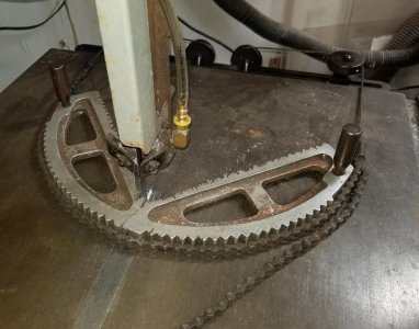
20220214_143100.jpg

Ready for a cut! Release the pedal and guide the cut with the work holder.
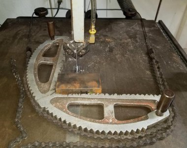
20220214_160344.jpg


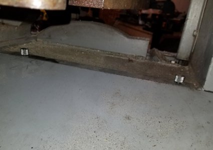
In normal use, the two removable pulleys are left off the mounting bracket as they set just above the table top. Naturally you can still push material into the blade with hand pressure, but the feed relieves you from having to apply pressure.


Thanks for looking, Bruce
 
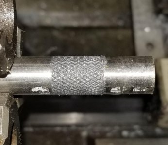
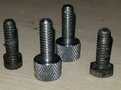
POTD part 2 was making a couple of knurled bolts to attach the back cover to my DoAll ML saw. I don’t know what was originally used by the factory; my saw had a ¼” hex-head bolt and a cap screw in place. I only run them in finger-tight, but what the heck.


"As I got it" fasteners to hold the back cover on my DoAll ML saw
20220214_144144.jpg


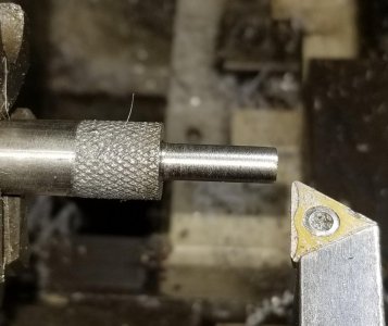
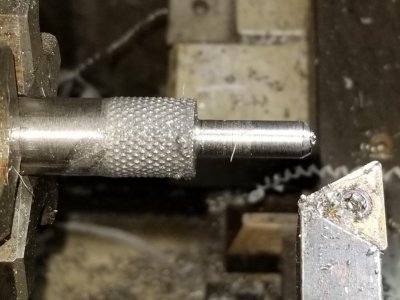
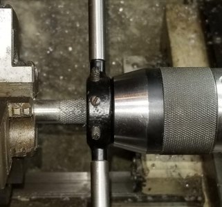
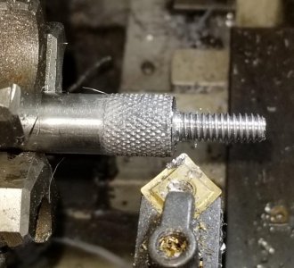
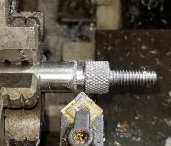
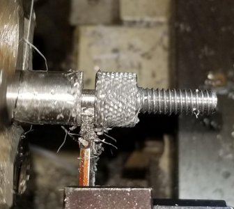
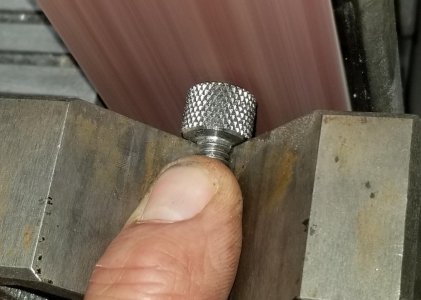
Material of choice was some ½” 303 stainless. Started with the knurl (Eagle Rock knurler). Then turned a shoulder to 0.244” and chamfered the end. Threaded with a die using the tailstock drill chuck to hold things square. Plunged in with a parting tool and chamfered both ends of the knurl, then parted. Cleaned up the nip from parting with a belt sander.


Eagle Rock knurling tool does a really nice job
20220214_144932.jpg
20220214_145005.jpg

Turned a shoulder
20220214_145917.jpg

Chamfer the end prior to threading
20220214_152046.jpg

Threading with a die using the tailstock/drill chuck to hold things square
20220214_152728.jpg

Chamfering the knurled ends
20220214_152934.jpg
20220214_153155.jpg

Parting
20220214_153354.jpg

Sanding the nib off the end
20220214_155559.jpg

Final products
20220214_155644.jpg

New bolts in place
20220214_155845.jpg


Thanks for looking, Bruce
 
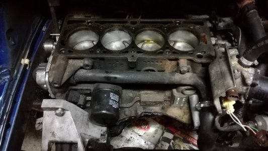
Today i was at work until dark but i wanted to make some progress on the Scenic, it's been in the garage too much time. Started by cleaning the engine block inside and out, from the top and from under. Then i oil the pistons, cylinders and new bearings i used my ring compressor and installed the pistons one by one and torqed them to specs. This was the easy part refitting the oil pump, new gaskets and apply silicone, to get the oil pan in place was very dificult i had to remove both engine mounts and lift the engine and box much higher. Tighten the oil pan bolts and started my fight with mounting the engine and box. To mount it took almost 2 hours by the time i was done i had time to wash up and go again to work. I was focused on the work and my hands were very oily so i only took a picture when i was done.
IMG_20220215_200713.jpg
 
Back
Top