
If that was a question for me, I got two of these 12" ones and cut the cross-slide one down to size https://www.amazon.com/gp/product/B00LOBCMCSso what ones did you install.

-
Welcome back Guest! Did you know you can mentor other members here at H-M? If not, please check out our Relaunch of Hobby Machinist Mentoring Program!
- Forums
- THE PROJECTS AREA
- PROJECT OF THE DAY --- WHAT DID YOU DO IN YOUR SHOP TODAY?
- Project of the Day Mega-Thread Archives
You are using an out of date browser. It may not display this or other websites correctly.
You should upgrade or use an alternative browser.
You should upgrade or use an alternative browser.
2018 POTD Thread Archive
- Thread starter 2volts
- Start date
OK, mounted the DRO screens properly. They have magnets on the back so just had to cut, bend and bolt on a backing plate on the splash shield. Then decided to build a tool height gauge. Wow the DRO made it so easy, I got it close with the saw, then for the final dimensions I just measured both the gauge and the correct tool height using caliper's dept gauge, subtracted the two to arrive at the delta, in my case .015". Then touched off, zero'd out the DRO, backed up, dialed in .015" on the DRO and took the cut. Done! No back and forth measuring, no eye balling, and no backlash issues. I had no idea how effective this simple and inexpensive mod could be to help my lathe work. I also ended up using my saddle-stop for turning that I recently made on my CNC mill. Truth be told, I never cared much for these little tools, widgets and jigs before but they definitely make a difference in speed, convenience and even accuracy. I'll be on the look out for more handy things others have made whether for the grinder, bandsaw, mill or the lathe.


F
Firestopper
Forum Guest
Register Today
Took apart the Aloris CXA cleaned,regreased and reassembled. Also replaced the old plastic ball.

Paco
Paco
- Joined
- Feb 8, 2014
- Messages
- 11,144
I bored a couple of timing sprockets today, these are for the turret drive and live tooling drive for my CNC lathe project. Normally something like this would not be worthy of posting, but in this case they required a bit of thought to hang onto for boring. There wasn't really enough hub to hang onto and they are a bit of a PITA to dial in under the best of conditions, you have to have the bore concentric with the OD of the teeth, and you can't chuck on the flanges. So I tried something a little different this time.

First some pie jaws for my 3 jaw. Didn't really need full pie jaws to hang onto the sprocket since i'm working in the center of the chuck but I might need them for a large hollow part someday
So start with a piece of 1/2'' aluminum plate. This is bolted down to two thickness of 3/4'' with 3/8-16 x 1 1/2 cap screws. Drilled & tapped the MDF. Normal drill for 3/8-16 is 5/16'' but in MDF I go one size smaller to get 100% thread depth. You can tighten the cap screws pretty tight without stripping if you have about 3 diameters or more of thread depth. The MDF is bolted down to the table and the top piece is screwed to the lower piece with drywall screws. The two Phillips head deck screws held the plate in position while drilling the holes. The center bolt goes down to a T-nut, adds a bit of security for the outside roughing operation.

And this is what happens when an end mill gums up with aluminum, it just kind of melts through the plate.

I should have been watching a bit closer, but I had my back to it working on the lathe. I basically did everything wrong here Using a 4 flute rougher rather than a 2 or 3 flute. Not enough coolant flow, let the chips build up, in addition to pushing it kind of hard. It actually overloaded the motor and tripped out the VFD, first time that has ever happened. But wait, there's more... The VFD fault output WAS NOT (it is now) tied into the E-stop circuit so the servos kept happily running along until I hit the E-stop. Of course moving the parts around and knocking the head out of tram. So tram the head, find 0 again and finish the cut. Surprisingly, the endmill did not break, nor was it damaged by the aluminum welding to it, cleaned right up and I finished the job with it.
Finishing the profile. I could have built the pie jaws with a drill press and a band saw, but it's just too easy when you have a CNC mill sitting there. I'm getting lazy in my old age.

And the mill work is done.

So next over to the lathe and prep them for use. First something in the center to you can load the jaws outward when tightening the cap screws. This is the ring I turned to preload the chuck jaws for boring the center to size. I should note here that my chuck jaws are removable 2 piece jaws, with single piece jaws you would not be able to do this. Interesting camera perspective, that's an 8 inch chuck, makes my hand and 5/16'' allen wrench look huge.

Then using the same ring in this case, tighten the jaws down on the ring to load them for boring to size. In this case the bore is a bit smaller than the ring because I needed clearance for the flange on the sprocket. So make the bore exactly the same size as the OD of the sprocket teeth. That way the sprocket is captured all the way around and held concentric in both axes, just like a collet.

So now ready to bore the sprockets to 22mm. I made them on size because I want them to shrink on. I'll heat them up pretty hot to install. Did pretty good, hit the target dimension dead on for one of them, and 0.0001'' under on the other. They started out at ~15mm bore.

And done with this part of the operation

So next is the keyways. the keys are 6mm and I don't have a 6mm broach, so time to make a quick keyway cutter. I grabbed a trashed brazed carbide bit, drilled a 0.358 hole (T drill) in the shank to clear the edges of a 1/4'' HSS lathe bit, and put a set screw in the end to hold the bit in place.

Then I ground the 1/4'' bit into a 6mm keyway cutter. I just did this by hand, grind a little bit, measure, rinse, repeat until it's correct. I managed to hit 6.01mm and decided that's close enough.
Cut the tool bit to length. Then just set up in the lathe and pretend that I'm a shaper.

So tomorrow back to the rest of the lathe project.
First some pie jaws for my 3 jaw. Didn't really need full pie jaws to hang onto the sprocket since i'm working in the center of the chuck but I might need them for a large hollow part someday
So start with a piece of 1/2'' aluminum plate. This is bolted down to two thickness of 3/4'' with 3/8-16 x 1 1/2 cap screws. Drilled & tapped the MDF. Normal drill for 3/8-16 is 5/16'' but in MDF I go one size smaller to get 100% thread depth. You can tighten the cap screws pretty tight without stripping if you have about 3 diameters or more of thread depth. The MDF is bolted down to the table and the top piece is screwed to the lower piece with drywall screws. The two Phillips head deck screws held the plate in position while drilling the holes. The center bolt goes down to a T-nut, adds a bit of security for the outside roughing operation.
And this is what happens when an end mill gums up with aluminum, it just kind of melts through the plate.
I should have been watching a bit closer, but I had my back to it working on the lathe. I basically did everything wrong here
Using a 4 flute rougher rather than a 2 or 3 flute. Not enough coolant flow, let the chips build up, in addition to pushing it kind of hard. It actually overloaded the motor and tripped out the VFD, first time that has ever happened. But wait, there's more... The VFD fault output WAS NOT (it is now) tied into the E-stop circuit so the servos kept happily running along until I hit the E-stop. Of course moving the parts around and knocking the head out of tram. So tram the head, find 0 again and finish the cut. Surprisingly, the endmill did not break, nor was it damaged by the aluminum welding to it, cleaned right up and I finished the job with it.Finishing the profile. I could have built the pie jaws with a drill press and a band saw, but it's just too easy when you have a CNC mill sitting there. I'm getting lazy in my old age.
And the mill work is done.
So next over to the lathe and prep them for use. First something in the center to you can load the jaws outward when tightening the cap screws. This is the ring I turned to preload the chuck jaws for boring the center to size. I should note here that my chuck jaws are removable 2 piece jaws, with single piece jaws you would not be able to do this. Interesting camera perspective, that's an 8 inch chuck, makes my hand and 5/16'' allen wrench look huge.
Then using the same ring in this case, tighten the jaws down on the ring to load them for boring to size. In this case the bore is a bit smaller than the ring because I needed clearance for the flange on the sprocket. So make the bore exactly the same size as the OD of the sprocket teeth. That way the sprocket is captured all the way around and held concentric in both axes, just like a collet.
So now ready to bore the sprockets to 22mm. I made them on size because I want them to shrink on. I'll heat them up pretty hot to install. Did pretty good, hit the target dimension dead on for one of them, and 0.0001'' under on the other. They started out at ~15mm bore.
And done with this part of the operation
So next is the keyways. the keys are 6mm and I don't have a 6mm broach, so time to make a quick keyway cutter. I grabbed a trashed brazed carbide bit, drilled a 0.358 hole (T drill) in the shank to clear the edges of a 1/4'' HSS lathe bit, and put a set screw in the end to hold the bit in place.
Then I ground the 1/4'' bit into a 6mm keyway cutter. I just did this by hand, grind a little bit, measure, rinse, repeat until it's correct. I managed to hit 6.01mm and decided that's close enough.
Cut the tool bit to length. Then just set up in the lathe and pretend that I'm a shaper.
So tomorrow back to the rest of the lathe project.
Last edited:
- Joined
- Jan 31, 2016
- Messages
- 11,413
Looks to be an outside day today so the tractor will come out of the garage , I'll sort out some more tools , clean up a bit and just enjoy the sunshine . I have 3 older IH cadets to restore this summer as well as many other projects around the shop and house . Can't wait till the weather finally breaks !
- Joined
- Feb 2, 2017
- Messages
- 1,234
Made a couple table covers for my new mill out of some scrap 3/4" walnut plywood. Gave them a coat of shellac to keep the walnut and steel from mixing (not sure if walnut has anything in it that would cause corrosion of the table, but the shellac should prevent it if it does).
Got my new Kurt vise and mill all trammed and square.

Started to rebuild my new-to-me Albrecht chuck, but got stuck without a way to bore holes the right size in the two aluminum clamps needed to hold parts for reassembly.
Got my new Kurt vise and mill all trammed and square.
Started to rebuild my new-to-me Albrecht chuck, but got stuck without a way to bore holes the right size in the two aluminum clamps needed to hold parts for reassembly.
- Joined
- Mar 12, 2014
- Messages
- 1,531
wouldn't attaching the cooler to the exhaust pipe actually pick up more heat from the exhaust? I would think you would put it away from a heat generating component.
EDIT: it's been pointed out that it's not an exhaust pipe..
Not sure Jeff, but it looks likes it hanging under the front part of the engine. maybe that is a tube that is part of the frame. ???
No thats an exhaust pipe for sure
Nope im wrong now that i looked closer at it. It looks like its attached to the nose of the vehicle. The giveaway is you can see the belts and pulleys. Prob support for the radiator. @Bill W. @woodchucker
Agreed, in the standard view the image info blocks that, but using the full size function, I see that now.
Obviously not an exhaust pipe.
Guys sorry, I've been off-site for a couple of days. The cooler is NOT attached to the exhaust pipe. In an earlier post that I believe was on the old "what did you do in your shop today" I mentioned that round tube that serves as a crossmember spanning left frame rail to right frame rail at the front of the Jeep. This is what I mounted the oil cooler to.
Thanks for looking and I should have carried that information over to this thread but I forgot the other one was closed/locked.
Mike
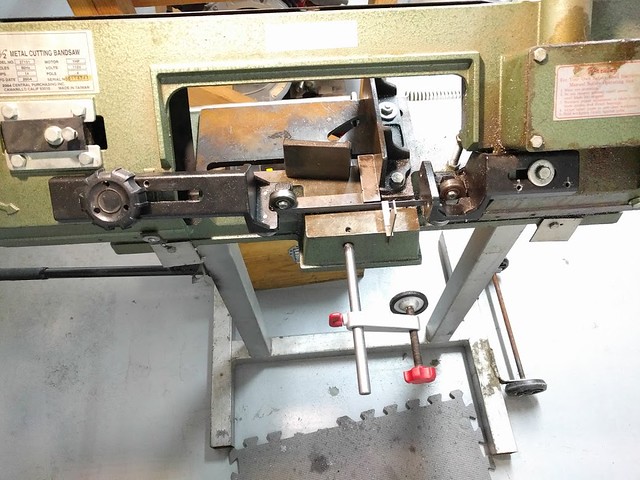
After 13yrs of ownership my HF 4x6 bandsaw finally cuts perfectly square! Yes, I purchased this as one of my two very first metal fabrication tools back in 2004, along with my Hobart welder. It never cut square no matter what I tried, I gave up on it and bought an abrasive saw, then a plasma cutter but always found the bandsaw more convenient especially for bar stock and tubing. Then recently upon looking into it again (after a few years of metal experience lol) I realized that the reason it never cut square was because it's missing two major adjustment points, the upper and lower blade guides don't twist/swivel to allow the blade to be vertical. So I checked the other HF saws and sure enough they all have this adjustment. It baffles me why this 'Taiwanese' saw didn't have one? Then as I started thinking about shimming it to get the blade correct I happened upon someone's YT video who came up with this idea and it works great. He drilled and tapped two holes and used set screws for the twisting adjustment. Sure enough, that got me pretty close but now I was on a mission so I did the same thing for the upper guide and I couldn't believe how accurate this saw cuts now even with an old blade that's been cutting at the wrong angle for years.
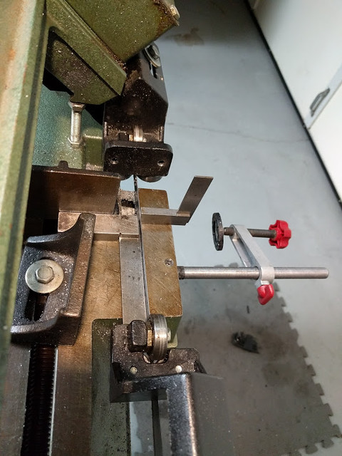
The set screws are on the (black) upper and lower blade guides - near the knob and the hex bolt respectively:
The blade sits perfectly square to the vise now- parallel and perpendicular:
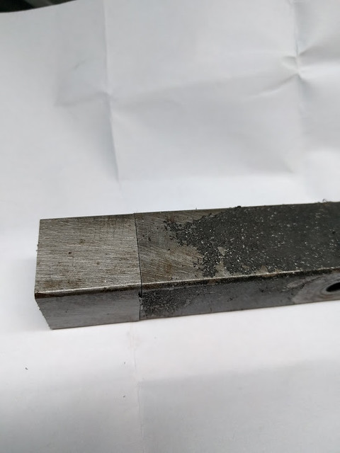
A test cut, flipped the cut piece 180deg and the fit-up is about as perfect as a bandsaw can make:
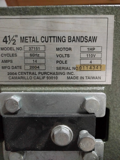
Hope this helps those with these odd-ball HF 4x6 37151 bandsaws from the past (presumably a bad run?)
The set screws are on the (black) upper and lower blade guides - near the knob and the hex bolt respectively:
The blade sits perfectly square to the vise now- parallel and perpendicular:
A test cut, flipped the cut piece 180deg and the fit-up is about as perfect as a bandsaw can make:
Hope this helps those with these odd-ball HF 4x6 37151 bandsaws from the past (presumably a bad run?)
- Joined
- Dec 22, 2015
- Messages
- 561
Not much machining in my shop for a while. I've been fighting with a leaking fitting on my skidsteer. Should have been an easy job to remove the fitting and replace it with a new one. But 3 things made sure that wasn't going to happen. Firstly, as someone on the tractor forum noted; a skidsteer is 10 lbs of stuff crammed into a 5 lb bag; secondly the fitting was located under the cab in an area where 2 people are needed or one guy with 4 arms that can all contort, in order to reach the part and thirdly the jam nut holding on was extremely tight. I was at this for a few days, for a few hours each day until I gave up in frustration. I ended up making some tools to get the job done and was finally successful. Sometimes stubbornness pays off.
Here is a pic of the fancy tools I made and the fitting that caused me so much grief.

The tool on the left was made so I could reach the jam nut and use a ratchet wrench on it. But even with a 1/2" breaker bar and a box wrench on the end of the breaker bar I couldn't get the nut to break free. The 3/8" thick steel plate the wrench was made of started to open up. The second tool is the winner and got the job done. It involved some machining. Even with this it took about 15 minutes of struggling to get the special socket over the fitting bend and onto the jam nut. There was just so much stuff in the way. After about 5 seconds with the impact wrench it finally broke free. The skidsteer is now out of the shop and seems to be working fine.
Here is a pic of the fancy tools I made and the fitting that caused me so much grief.
The tool on the left was made so I could reach the jam nut and use a ratchet wrench on it. But even with a 1/2" breaker bar and a box wrench on the end of the breaker bar I couldn't get the nut to break free. The 3/8" thick steel plate the wrench was made of started to open up. The second tool is the winner and got the job done. It involved some machining.
Even with this it took about 15 minutes of struggling to get the special socket over the fitting bend and onto the jam nut. There was just so much stuff in the way. After about 5 seconds with the impact wrench it finally broke free. The skidsteer is now out of the shop and seems to be working fine.