2020 POTD Thread Archive

It is a lock for the cross slide, the stock gibs lock is covered by the DRO scale. The cross slide lock bolts to the follow rest holes, so easily removed if needed. I uses a bronze lock which pushes against the cross slide, so quite secure and will not wear the cross slide. When my lathe was new and a bit stiffer I did not have an issues with creeping of the cross slide, but as it got worn in I did have some small changes. I also made a similar lock on my 1340GT and used it for many years. I find it much easier to use. I posted this one in the following thread:
 
I decided to make my own studs for my turbo with a spacer. A regular bolt won't work because they're too long to go through the bolt hole on the exhaust housing. I used 1/2 rod turned down to 7/16.
 

Attachments

  • 20200330_173058.jpg
    20200330_173058.jpg
    1.5 MB · Views: 43
  • 20200330_174134.jpg
    20200330_174134.jpg
    1.6 MB · Views: 36
POTD was continuing the work on the enclosure for my Tormach mill. I decided to go with front doors that will have slider doors, but will be on a frame that's hinged so the door frames can be swung open to give full access to the mill.

Started by turning some Delrin bushings to fit into the tubular framed doors. Simple lathe job, turn the OD to a snug fit in the Creform tubing, face, chamfer, center drill and drill hinge pin holes.


Face/chamfer the bushing
20200328_151112.jpg

Parting
20200328_151257.jpg

Center drill and drill a hinge pin hole
20200328_153405.jpg20200328_153510.jpg


The corners of the enclosure frame will have 1/4" hinge pins. Plan is to have a fixed pin on the bottom and a removable one up top. The door frames will be removed by pulled the upper pin, then lift the door off the lower pin. Naturally, with the hinge they can be swung open too.


Drilling a 1/4" hinge pin hole in the Creform corner bracket.
20200328_154634.jpg

Bushing fits over the hinge pin. Door frame tubing fits over the bushing.
20200328_155844.jpg


Upper door frame hinge pin will be removable. Plan was to have a bushed hole for the hinge pin.


Drilling the upper bushing hole (F drill for an 0.257" hole for some clearance to the 1/4" pin).
20200328_161255.jpg

Turn the OD to 1/2"
20200328_162044.jpg

Parting
20200328_162236.jpg


Chamfered a lead-in on the top of the bushing.
20200328_164520.jpg

Drilled a 1/2" hole through the upper corner brackets for the hinge pin bushings.
20200328_164243.jpg


The upper hinge pins were made from 1/4" 303 stainless. Started by running a 1/4"-20 die over the end.
20200328_170252.jpg20200328_170323.jpg

Parted and flipped, then chamfered the lead-in end.
20200328_170854.jpg


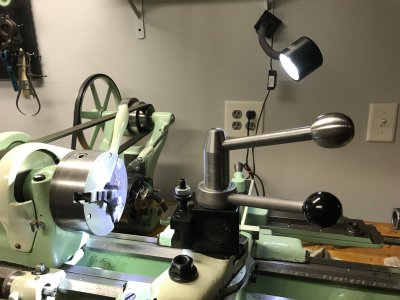
Next, made a couple of knobs for the removable hinge pins from aluminum. Did a clean up pass, knurled, tapped and parted. Finished the faced end by screwing the 1/4" pin in place, then chucked and faced.


Clean up pass on some 1" aluminum
20200328_171236.jpg

Knurled
20200328_171454.jpg

Center drilled, tap drilled, tapped and parted.
20200328_171539.jpg20200328_171654.jpg
20200328_171809.jpg20200328_172033.jpg

Facing the parted end and the final two upper hinge pins.
20200328_172735.jpg
20200328_172952.jpg


Upper hinge pin into the door frame bushing. The door can be removed by pulling this pin, then lift the door off the lower hinge pin.
20200329_132450.jpg

Door frame lower hinge pin.
20200329_132457.jpg


Door frames in place. The center area will have door panels that slide open for quick access. The door frames can swing open for full access to the front of the mill.
20200329_125919.jpg20200329_130022.jpg


As you can see, lots more to do:

Locking pins to hold the door frames in the closed position.
Move the monitor/keyboard swing arm to outside the enclosure.
Fab up a rail system for the front sliding doors.
Make a work table for the overhang at the front of the mill.
Make splash shields for the end panels, and the removable end panels.
Fab up a top.
Shower curtain for the back wall.
Mount the Mistaway air filtration system up top.

Probably a few more things I've forgotten, but am making some progress. Thanks for looking,

Bruce
 
POTD was making some T-nuts for a Grizzly 7" x 10" tilt table. The T-slots are about 1/2" wide at the top, but the bottom is narrower than what's on my Jet JVM-830 mill, so couldn't use standard 1/2" T-nuts on the table.

Found a piece of 3/4" CRS in my scrap bin. Wrote a quick routine for the CNC Bridgeport to cut the rabbets on the sides.


No hand cranking with CNC, plus an hman chip collector to keep the mess down.
20200329_135159.jpg


After the profile was cut, spotted, tap drilled, and power tapped 5/16"-18 holes.


spotting
20200329_140844.jpg

tap drilling
20200329_141407.jpg

tapping
20200329_141906.jpg

finished row of 4 nuts
20200329_142037.jpg

fit check in the tilt table. Top of the nuts are about 0.010" from the surface.
20200329_142226.jpg


Then to the band saw to cut them apart. I use a small vise to hold short parts when cutting. You can't see it, but there's a block of the same width as the vise on the opposite side of the saw clamp plate to even out the pressure. And YES, a smarter person would flip the vise 180 degrees so the cutting action is pulling the work into the vise, not out of the jaws. . . Fortunately, my lack of attention to details didn't bite me.

20200329_142729.jpg
20200329_142738.jpg


Cleaned up the T-nuts on a 2"x42" belt sander and grinder with a Scotchbrite wheel. Then peened the bottom end and for good measure buggered up the threads with a tapered punch. Didn't want a stud or bolt going completely through the nuts.
20200329_144023.jpg

Finished T-nuts
20200329_144308.jpg


Thanks for looking,

Bruce
 
Last edited:
I finished my Aloris tool post nut-handle. I made the ball on the handle from 304 stainless today. I plan to “blue” the nut and handle (which are hot rolled steel). Looking forward to not having to look for the wrench every time I want to adjust the tool position.
 

Attachments

  • FBBFC06D-781F-4983-B171-E94B6D5FC983.jpeg
    FBBFC06D-781F-4983-B171-E94B6D5FC983.jpeg
    2.2 MB · Views: 30
Another hobby is the yard irrigation system. Somewhat complicated and part of it is pressure control.

It has 3 regulators with 2 that have bypass controls.

There are 5 lines from the main connection with 4 on lowest pressure regulator and the other having 3 possibilities.

Main line comes in via main valve, then a 35 PSI regulator followed by a 25 PSI regulator (both of these have bypass valves).

After the 25 PSI regulator the system splits, main line for yard goes one way and an adjustable regulator that feeds the 4 lines in the garden goes the other way.

Rebuilt the pressure system this year as the bypass valves were bad.

Fully servicabl e noe as we added a bunch of split unions.

But the meters were all over the place.

Sun faded too.

Needed a manifold for mounting meters, wanted a chunk of aluminum but could not find one anywhere.

Scrap yard only had sheet but they had some round stock that planted the seed...

Checked the plastic supply and noting there in the scrap bin.

So back home and we find in the supply pile a chunk of what once was a ram, some sort of nickel steel threaded on the end, about 1.3 diameter and long enough.

Had some swivel 90 degree hose fittings for connection to the system.

We discovered this stuff is a bugger to tap pipe threads.

We cheated a bit, we found one 1/4 pipe tap that had some missing teeth so we ground off about 1/4 inch from the end.

This allowed it to only cut part of the threads, then we would use a different tap to cut the bottom, it was slow but we finally got all tapped.

Next is the box to put it in.
4203a43d65a55927a76f95dd6a288712.jpg
9dcf34829ade3a0fc98288f9192ebc55.jpg
7852fad1e3970a8c848ef43794289555.jpg
eb60a13a9bedcf5d92d165d6ae7be128.jpg


Sent from my SAMSUNG-SM-G930A using Tapatalk
 
I made a BXA dial indicator holder today. I was inspired by @stioc and @Janderso and other designs I've seen in this thread. I designed it so that the indicator can be reversed on the block. That way I can put it on the toolpost in the facing orientation and used to indicate the face of something too.

I don't have a dovetail mill so I used a 3D function in Fusion 360 with a 1" x 1/16" T-slot cutter to cut the dovetail. I used .002" DOC so it took about 16 minutes just to shape the dovetails.
 

Attachments

  • IMG_7552.jpg
    IMG_7552.jpg
    1.4 MB · Views: 33
  • IMG_7554.jpg
    IMG_7554.jpg
    1.3 MB · Views: 27
Back
Top