Power feed for Atlas/Craftsman 618 Lathe

SG51Buss

Active User
Registered
Joined
May 20, 2014
Messages
191
Power compound feed for Atlas/Craftsman 618 Lathe

Well, it's time for me to contribute something to this forum.

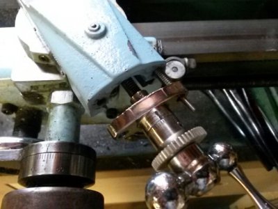
So, here's a powered compound project for my Atlas/Craftsman 618, Sears model 101.07301 lathe.

I wanted something very compact, that could be left in place without disturbing normal lathe operation. It needed to have forward and reverse, plus be disengaged when turned off. I also wanted the feed rate to be very slow, about 0.002" - 0.003" per revolution. Not really intending to do any cutting with it, just for precision feeding of a small toolpost grinder. I need to be able to make precise tapers. Slowly feeding the compound by hand is tedious, and introduces position errors because of the influence of hand feed pressures.

For me, these kinds of projects tend to hit stumbling blocks. This one started out semi-planned, with wiggle room to back up and rethink things.

What is presented here is the cleaned-up finished/workable version, without the goofy foul-ups and reworks that add color to our language.

With the exception of the hobby gearmotor and screws, just about every part is hand carved or dug out of boxes of ancient collections. As such, I don't expect this to be easily copied. But it is offered as an example of what could be done, and I hope others can find some useful ideas here.

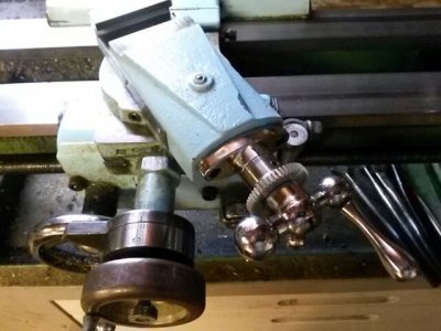
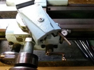
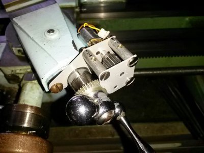
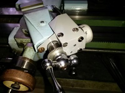
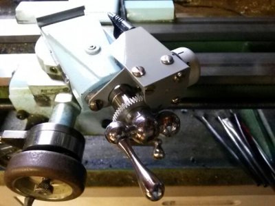
Here's a typical Atlas/Craftsman compound. The feed handle is a modified, slightly larger cross-feed handle.
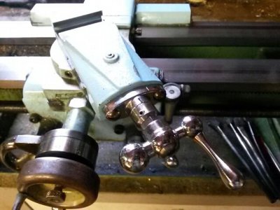
PowerCompound-01.jpg

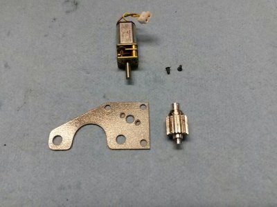
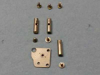
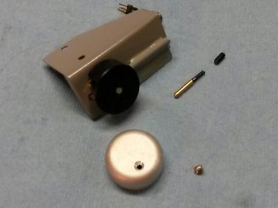
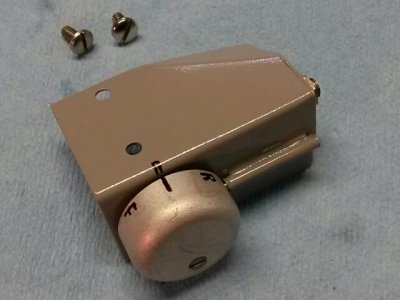
Here's all the parts to convert the compound feed to a powered compound feed.
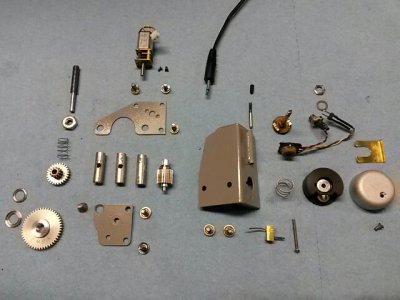
PowerCompound-02.jpg

The hobby gearmotor is a cheap eBay item. It turns about 100 rpm, which I wanted to slow down to about 20 rpm, about 1 inch per minute feed rate.

PowerCompound-01.jpg PowerCompound-02.jpg
 
Last edited:
Modifying the Compound feedscrew assembly

Remove the compound feedscrew assembly.
PowerCompound-03.jpg

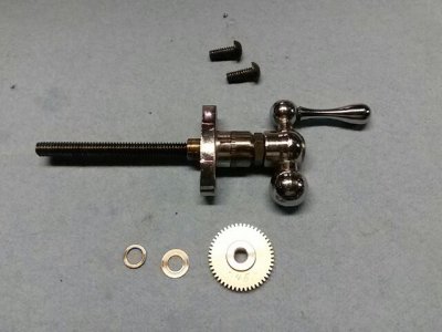
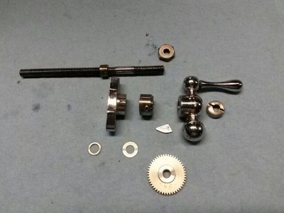
Disassemble the feedscrew assembly. Thin/polished thrustwashers will reduce friction. The large locknut will be replaced with a threaded gear.
PowerCompound-04.jpg

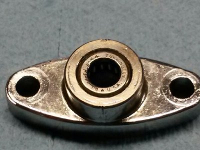
A roller bearing is fitted to the feedscrew boss.
PowerCompound-05.jpg

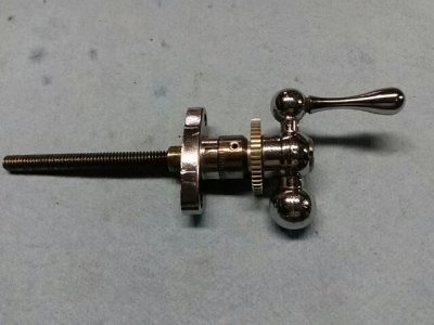
Reassemble the feedscrew assembly. To get minimum lash, screw the gear up to the loosened dial, fit and snug the crank handle, then firmly finger-tighten the gear back onto the crank handle. Try to achieve very light rotating drag.
PowerCompound-06.jpg

Trial fit the new compound feedscrew assembly. Check backlash and freedom of movement.
PowerCompound-07.jpg

PowerCompound-03.jpg PowerCompound-04.jpg PowerCompound-05.jpg PowerCompound-06.jpg PowerCompound-07.jpg
 
Backplate assembly

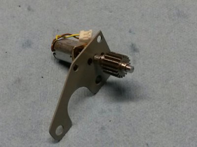
Mini gearmotor, backplate, and drive gear
PowerCompound-08.jpg

Assembled
PowerCompound-09.jpg

- - - Updated - - -

I found this motor at Robotshop.com which I purchased two of to control the mirror position on my telescope.
Pierre

http://www.robotshop.com/en/cytron-12v-12rpm-166oz-in-spur-gearmotor.html

Thanx, Pierre. I like the offset output shaft. I have a couple similar to that. They'll be involved in a later project, powered cross slide feed.

- - - Updated - - -

Fitting the backplate drive sub-assembly

#1 - The idler gear shaft replaces the right mount screw, and is fitted like a stud into the compound.
PowerCompound-10.jpg

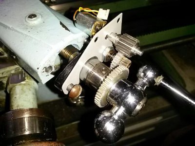
#2 - The feedscrew assembly is fitted and run halfway up the idler shaft. This leaves room for the drive sub-assembly to be partially installed.
PowerCompound-11.jpg

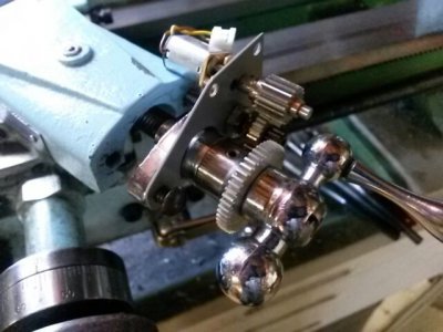
#3 - The backplate/drive unit is installed, nut fitted over the idler shaft, followed by the idler spring and idler gear.
PowerCompound-12.jpg

#4 - Flash photo shows a little better detail of this pre-assembly step.
PowerCompound-13.jpg

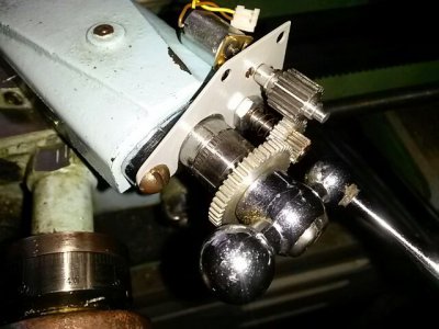
#5 - The compound is slowly/carefully slid back, while running down the studnut and ensuring that the backplate, idler spring and idler gear aren't binding. When the feedscrew boss is fully seated, the left mount screw is fitted. Then the studnut and mount screw are evenly tightened.
PowerCompound-14.jpg

Gently press the idler gear forward against its spring, disengaging it from the leadscrew gear. Check for proper operation and freedom of travel of the handcrank and leadscrew.

- - - Updated - - -

Front plate assembly

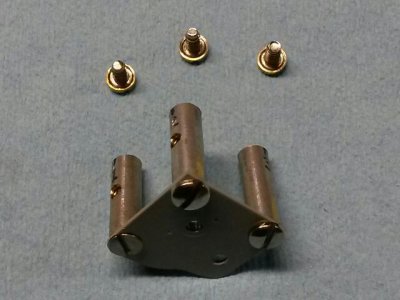
#1 - Front plate, spacers and screws
PowerCompound-15.jpg

#2 - Front plate sub-assembly
PowerCompound-16.jpg

#3 - Front plate and spacers fitted to the backplate. Ensure proper fit of idler shaft and drive gear pinion.
PowerCompound-17.jpg

Check for smooth sliding action of the idler gear. Ensure that it slides sufficiently to fully/easily engage and disengage the feedscrew gear, while maintaining engagement with the drive gear.

- - - Updated - - -

Coverplate and control switch sub-assembly

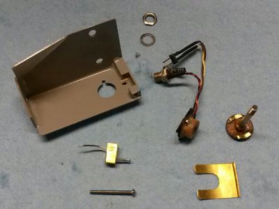
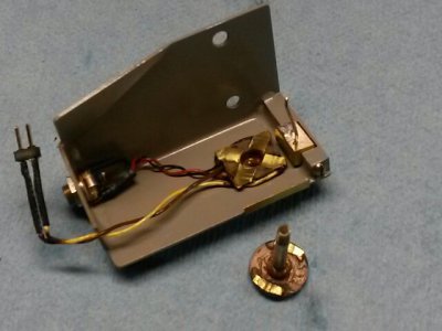
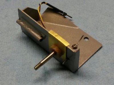
#1 - Coverplate, reversing switch, retention clip, and pivoting disengagement finger
PowerCompound-18.jpg

#2 - Reversing switch base and power socket are fitted. Retention clip holds the switch to the coverplate. Pivoting disengagement finger is fitted.
PowerCompound-19.jpg

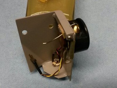
#3 - Outside view. The protruding pin of the pivoting disengagement finger will ride on a cammed profile of the switch knob.
PowerCompound-20.jpg

- - - Updated - - -

Coverplate and control knob assembly

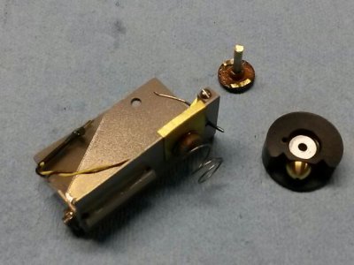
Switch rotor, pressure spring and control knob. The spring ensures good electrical contact of the rotor shorting fingers
PowerCompound-21.jpg

The control knob has a cone-shaped screwhead which acts as the actuating cam for the disengagement finger's actuating pin. The switch rotor and control knob must be assembled such that the rotor is in mid-noncontact (off, no current) while the control knob's cam peak is aligned with the disengagement pin.
PowerCompound-22.jpg

Shellcover for the control knob and detent plunger.
PowerCompound-23.jpg

Shellcover and detent installed. Check for freedom and cam-following of disengagement finger movement while turning control knob.
PowerCompound-24.jpg

The control knob rotates +/- 45° for 3 positions:

Forward -- Disengagement finger released, positive polarity of current to gearmotor
Off --------- middle position, disengagement finger pressed to slide idler gear out of engagement, no power to gearmotor
Reverse -- Disengagement finger released, reverse polarity of current to gearmotor

- - - Updated - - -

Final assembly of coverplate and control knob

Connect gearmotor wiring, fit coverplate onto gearing sub-assembly while ensuring that disengagement finger fits against the sliding idler gear. Tighten screws.
PowerCompound-25.jpg

Flash photo to show better detail.
PowerCompound-26.jpg

- - - Updated - - -

Powered compound functional test

Here's a video of the Powered Compound functional test.
If you look closely, you can see the edge of the idler gear sliding into and out of engagement.

Http://youtu.be/yeorJAN2CGs

(*whew*)

PowerCompound-08.jpg PowerCompound-09.jpg PowerCompound-11.jpg PowerCompound-10.jpg PowerCompound-12.jpg PowerCompound-13.jpg PowerCompound-14.jpg PowerCompound-15.jpg PowerCompound-16.jpg PowerCompound-17.jpg PowerCompound-18.jpg PowerCompound-19.jpg PowerCompound-20.jpg PowerCompound-21.jpg PowerCompound-22.jpg PowerCompound-23.jpg PowerCompound-24.jpg PowerCompound-25.jpg PowerCompound-26.jpg
 
Nicely done, and documented. I guess it proves the old saying "Where there's a need there's a feed" or something along that line. :) Mike
 
Back
Top