power hacksaws mechanisms/hydraulics

ecosta

Registered
Registered
Joined
Jul 14, 2017
Messages
7
Hi guys,

I've been looking at homemade power hacksaws this weekend, as I've been thinking on building one.

In one hand, I'd like to know if there is any literature, manuals or pointers on mechanisms/methods used on these machines. I'm mostly interested in:

* Adjustable blade lifting for the part of the cycle where it's not cutting, so the blade lasts longer.

* Mechanical/pneumatic/hydraulic methods for power feed. Most of the videos I watched on yt show home-built machines that take much longer to cut a piece of rod than one would do manually, plus that I'm not a real fan of simply dropping some weights at the end of the arm just for the sake of it, so looking for some adjustable power-feed systems.

* Methods for stroke-length adjustment. I know the basics, but if there's more info about it, much better.

In the other hand, I'm pulling my hairs out with this two videos:


The first one shows the construction of the power hacksaw, while the second shows it working.

This simple but clever design does everything I want to, lifts the blade for the part of cycle it's not cutting, offers adjustable power-feed so that no weights are needed, and it even lifts the arm once it's done. But I don't fully understand the hydraulic circuit.

I can see the tank made out of hollow square tubing, a cylinder (probably out of a hydraulic jack) acting as a pump, a closed loop cylinder-to-cylinder jig showing the Pascal principle to mechanically act up on a ball-valve (that never fully opens), an adjustable 3-way flow valve, and the one-way hydraulic cylinder which does all the job (blade lifting/power-feed while cutting, and arm-lifting once it's done).

Now, I've been trying to follow the tubing, draw it on paper, adding check-valves here and there, but I miserably fail to reproduce it.

I'd say the ball-valve sits between the cylinder and the 3-way valve, whose other inlet is the tank itself, and whose output is the pump's inlet.

While cutting, one only needs adjust the 3-way valve for the pump to suck fluid with more o less strength out of the cylinder, hence allowing for adjustable power feed.

This makes sense because when the pascal-rig closes the ball-valve at the end of the cutting process, all the flow for the 3-way valve would come from the tank, but I'm missing how the pump output gets redirected to the cylinder (so it raises), and also how it is that while cutting each pump stroke causes the arm to lift a bit.

So if anybody reading this is used to hydraulics and can explain, I'd really appreciate, or if there's some literature about power hacksaws and it's mechanisms.

Thanks!
 
I have a Keller power hacksaw from somewhere in the mid 50's to early 60's. It has a mechanical ratcheting mechanism to provide a little bit of blade lift on the return stroke. The parts for the system are worn and sloppy, thus little pressure if any is taken off of the blade on the return stroke due to all of the lost motion. I too would love to get my hands on a detailed plumbing schematic for a hydraulic system as shown above so that I could maybe design something similar for my Keller. I have my suspicions about the system, but I am not certain that they are correct.

For downward cutting pressure, the Keller has a fairly heavy saw frame to begin with, but also has an adjustable spring tension system in the base of the saw so that the pressure on the blade can be adjusted from very little to quite a bit. Enough that I have to grunt to pick up the saw frame. Spring tension is adjusted with a hand wheel and the system works quite well. This saw will cut through a piece of 2" diameter 4140 steel rod in just a matter of minutes. I have never actually timed it, but if the pressure is set correctly I would say that it cuts it in three or four minutes.

ON EDIT: I don't think it would be necessary to be able to adjust the stroke of the blade. I cannot say that I've ever seen a power hacksaw that has such a feature.

I finally took the time to think through the hydraulic circuit and drew it out on paper. Turns out it is a very simple system, it just looks more complex than it really is. I am working on a drawing of the system that I can post here.
 
Last edited by a moderator:
Hi guys, thanks for your answers.

I know adjustable stroke exists, even together with blade length adjustment. I'm aiming for this mostly because I've noticed many power hacksaws wear the blade on one side mostly (or in the middle), so by being able to adjust it the whole blade can be employed, or part of it used if not yet worn out.

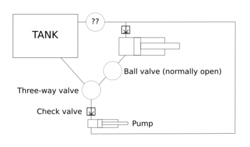
I'm looking forward to see what you come up with Terry, I've also made a drawing you can find attached (I don't know how to place it inline), to try to explain better how I understand what I see on the videos.

As seen in the picture, and providing pump's stroke is in sync (there might be some pressure built up by the time the cutting part of the cycle starts), it will drain fluid from the cylinder and the tank, in amounts given by the position of the three-way valve, which should cause the cylinder to retract, hence exerting pressure on the blade for a stronger cutting.

Because the pump has a check-valve on it's inlet, the fluid would be sent back to the tank, while letting some pressure enter the cylinder, which is what causes the blade to lift for the part of the cycle it's not cutting.

This dampening effect, and the reason I put two question marks on the tank's return line, is what I don't know how to achieve, and I didn't see anything leading me to it on the videos (perhaps he's using different tube diameters, or also a check-valve on the tank whose working pressure is higher than the cylinder's check-valve pressure?)

When cutting is done and the ball-valve closes, the pump would drain from the tank only, through the three-way valve to the the cylinder, hence lifting the arm, and again, given my circuit and what I can see on the videos things don't match or I'm missing something.

In either case, I we cannot solve it here, I'll try asking him and see if he answers.

Regards,

text3955.png
 
Hey guys,

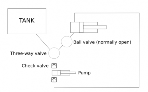
What about this one? My previous drawing was wrong anyway.

Now the return path is the same as the pressure path. Now I understand why the ball-valve was never fully open, it restricting the flow on the return path causing the blade to lift, so the lift is adjustable!

What you reckon?

Regards,

text3956.png
 
I am currently on the road, should get back home tomorrow evening. I will post my drawing then. Ecosta, your drawing isn't too far off, but it isn't quite correct, either.

First, a quick lesson on hydraulics. Pumps never 'pull' a cylinder by sucking oil out. Everything in hydraulics is done with positive pressure created by the pump, which moves oil to create that pressure. I can do a better job of explaining from my computer keyboard at home. Typing out such an explanation from my phone is far too tedious. I will upload my drawing and explanation when I get back home.


Sent from my SM-G360T using Tapatalk
 
Okay, I am back home and, as promised, am writing on what I figured out about the hydraulic lift system in the video. I have seen other saws with similar systems in the past, but never close enough to determine what components were used or how the system worked.

One thing different about this saw is that the motor gets shut off when the saw reaches its upper most position instead of when it hits the bottom.

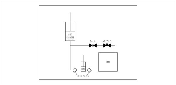
In this system, anytime the saw is running, the pump is pumping oil. The resulting movement of the saw arm depends on two things: how far open the needle valve is, and whether the ball valve is open or closed. The hydraulic system only lifts the saw arm, it does nothing to increase the cutting force on the blade. The only thing pushing the saw arm and blade downward is the saw's own weight.

The two check valves shown in the drawing could optionally be built into the body of the pump cylinder in place of being separate components.

1. When the ball valve is open, and the needle valve is all the way open, the saw arm will drop because the valves pass oil faster than the pump can pump it through the system.
2. If the ball valve is open and the needle valve is open only a tiny bit, the arm drops slowly but pulses upward when the pump plunger forces oil into the system. This happens because the needle valve is set at just such a point to create the desired action.
3. If the needle valve were closed completely, the effect is the same as closing the ball valve: The saw arm will rise in 'pulses' as the pump plunger pumps oil into the system. This will continue until the arm reaches maximum height and its limit switch shuts off the motor.
4. The system used to close the ball valve in the video is hydraulic also, but it could be done with a mechanical system just as easily. Either way, the result is the same: the saw frame rises until the motor shuts off.
5. Careful adjustment of the needle valve is required to get a steady drop of the saw arm and blade, interrupted by a slight lift of the blade on the back stroke.
6. Sizing of the pump and cylinder must be considered very carefully in order for this system to work as intended.


Power Hacksaw Hydraulic Lift System.JPG


Like I said earlier, it is actually a very simple system! Let me know what you guys think.
 
I have a Kasto power hacksaw, it uses a hydraulic feed system. The cylinder is at the rear of the saw, further back from the pivot point, so as the cylinder extends, the saw blade goes down. The cylinder I'd single acting, hydraulic pressure to extend and a spring inside the rod end of the cylinder to retract the cylinder, and lift the blade.

The reciprocating movement of the blade is mechanical. The blade lift for the return stroke, is done with the hydraulic cylinder - a very clever arrangement. The hydraulic system uses two small single piston pumps - about the size of the pump in a regular grease gun and the run off a cam on the same shaft that is driving the saw (one pump per stroke of the saw).

One pump is for the feed. Pretty standard - control valve and check valves. It adds oil to the bottom of the ram and the blade is fed into the work. The second pump is just a solid connection to the oil side, no check valves - it adds and removes one pump stroke with each saw stroke and the cam is timed so that it adds oil for the cut stroke and allows oil out for the return and the spring in the rod end of the cylinder retracts the cylinder a small amount (about one millimeter). It works really well, you can run the saw up well over 100 spm and the retract works fine.

About wearing just one part of the blade, Kasto thought of that too. You can slide the back jaw forward or back. Of course, you have to pay attention, for a wide section, you need to push the jaw right back, or the frame will hit the work piece.

Search Kasto PSB on this site, you will find pictures of my saw.

Good luck with your build. David
 
Hi guys,

David: thanks for your comment and for your explanation, I think I more or less got it. I like the idea of having dedicated pumps, the cylinder acting behind, and also using a spring.

Terry!: haha, that's about the same as mine's? The only actual difference is you are using a needle valve and pumping, not bleeding.

You circuit looks alright to me, but It's so close to the original that I think I'd be going for the former, because it has one more feature.

As I understand it, and up to certain limits, the wider the stock is, the more pressure one might need to exert on the blade when cutting, though other factors such as how coarse or fine it is also play a role on this.

So if all you have is your arm's weight, you'll probably get proper flakes and normal cutting-times with thin stock, but dust and longer cutting/rubbing times as it gets wider.

If I got David right, even Kasto uses negative pressure, and that's probably because designing the whole thing for the opposite would make it as complex and expensive that it would be overkill right up front.

Perhaps even and off the shelf cylinder might be ok, because the lip seal at the other side might expand (and seal) under negative pressure on it's back, but it shouldn't be rocket science to build one if that doesn't work. If using a bottle jack pump, one should look if it can stand negative pressure and amend if it doesn't.

Talking about the original circuit now, I don't like the fact that pressure and relief paths are the same, because it inter-relates everything and probably results in poor/little regulation.

In fact you can notice on the second video how the lift lessens when he applies more pressure to the blade, so dedicated pumps could be a solution here (you can also notice that he uses weight on the arm, because the pull from the cylinder alone just doesn't cut it).

I agree with you Terry on the fact that the pump and the cylinder are going to need some numbers.

Also, the *added bonus* of lifting the arm once it's done, which is actually a side effect on this circuit, well, I might not want it every time, overall if I leave the machine unattended while cutting some chunky stock.

So either I'll come up with a friction clutch or I'll see, don't know yet. I also prefer pure mechanical actuation over the ball-valve over the pascal thing, the accuracy this offers does nothing here.

To both, the original circuit and yours, Terry, I'd add a safety valve such that in case the limit switch doesn't do it's job, all the pressure the pump might want to build while is manually turned off goes back to the tank and not over the floor, or cause any major mechanical damage.

In my case, I'm going for a bench-top design. 50 cm. stroke max, and plan to use only regular handsaw blades (which I plan to drill, say, 10 cm. before the end so that I can have a more flexible stroke).

I'll see if I can post some pictures tomorrow of the arm I'm designing, would like to know what you guys think about my approach.

Regards,
 
Hi Guys,

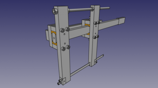
As I said yesterday, wanted to upload a couple of pictures of what I have so far.

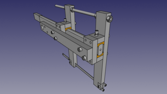
This is a view of it from it's back:

back.png

The saw is shown at maximum stroke. The only thing I'd need to buy is brass for the bushings (orange), but I only have a 9x20 lathe to build it, hence the design.

I've never made or seen (that I recall) sliding mechanisms like this, but it seems to me like it would work, so I'll give it a try, and if it happens no to be suitable for a hacksaw, I'll use it for a tapper attachment at the lathe.

As you can see, the arm is square stock which I'll center drill, clamp it on the 4-jaw chuck, live center on the center drill, and give it a couple of passes until I remove the square.

Then I plan on doing a slotting mill with the needed radius out of mild steel, which I'll heat-treat so that I can mill a couple of brass bushings on the lathe at once out of square brass stock.

Viewed from it's front now:

front.png

You can see four holes without screws, these are oiling ports, I'll probably used 90 degrees bent nipples with pneumatic plastic tubing, that I'll use with a hand pump somewhere on the saw to lubricate the bushings even while in operation.

The threaded rod at the top is to counter-effect the blade tensors at the bottom so that the bushings run parallel to the arm.

What you guys think?

Regards,
 
Back
Top