Precision Matthews PM-728VT CNC conversion

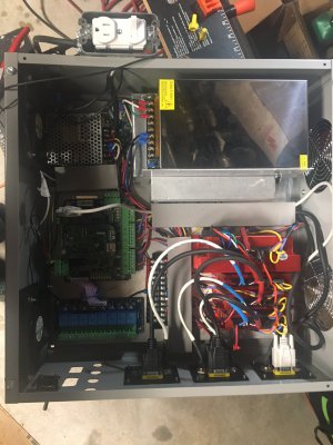
Picture of the CNC control box about half way wired. All 4 stepper drives are at lower right. Two large power supplies (36 & 48V) are at the upper right. Acorn power supply, Acorn board and Acorn relay board are at left. Fans are at the left side which will become the bottom. Outlets are at the right in the picture (will be top).

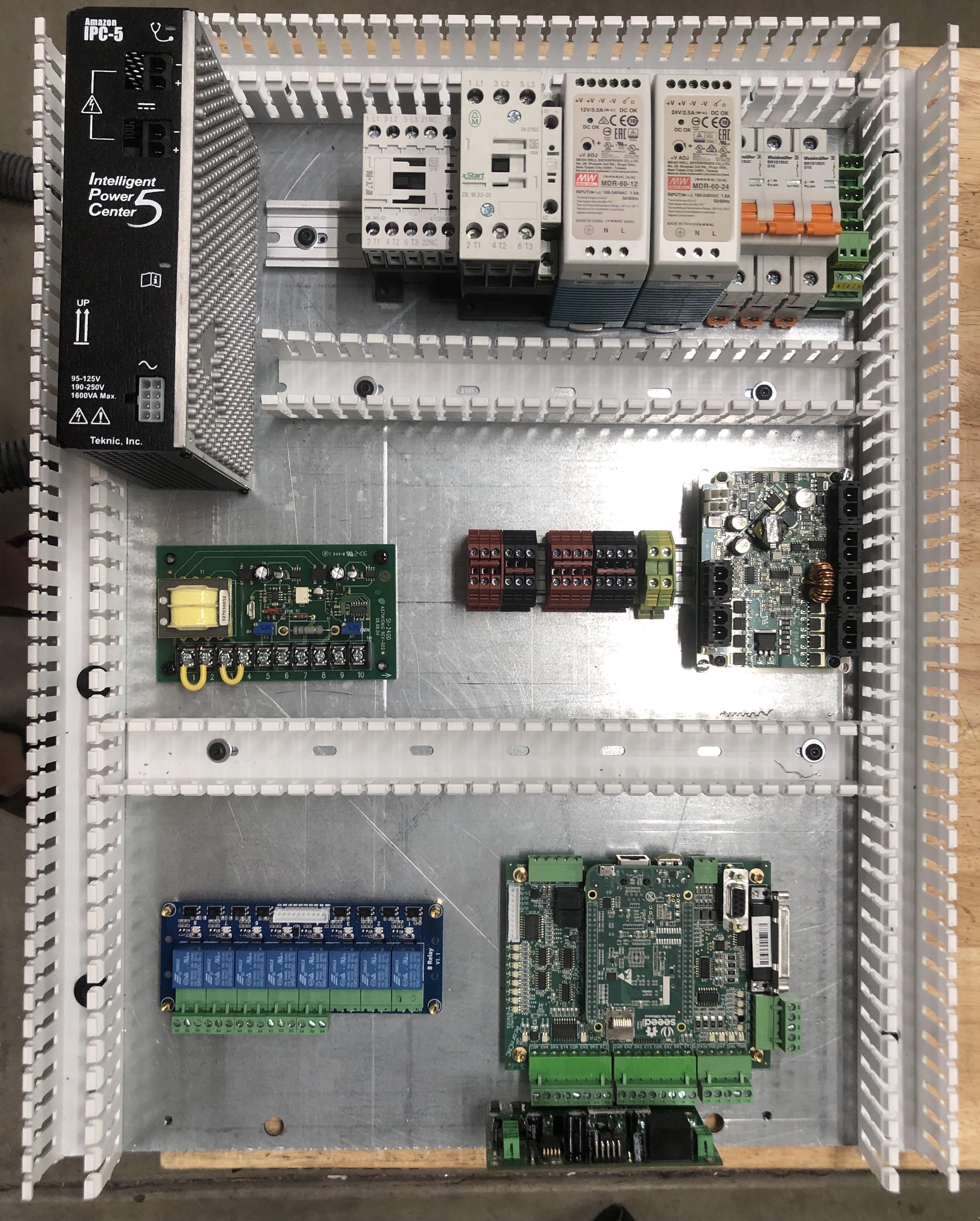
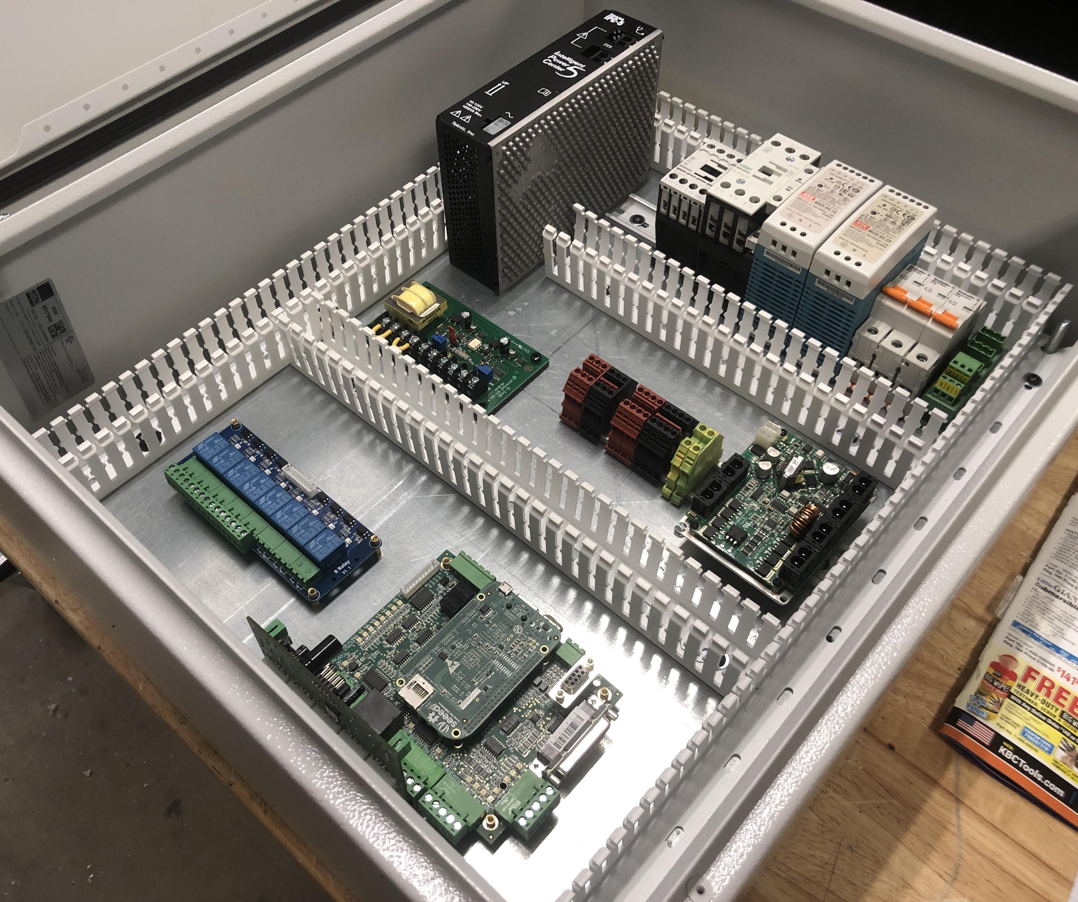
The box is 18x18x6. If I had it to do over I would go with a slightly larger box (20x20 would help a lot). I got it all in there but it is tight. I had to stack the two large power supplies so I added a heat sink to the 36V and bolted it to the aluminum base plate.

I keep thinking I will 'finish it this weekend' but then something comes up and I don't get much if any time to work on it.
 

Attachments

  • CNC wiring box.JPG
    CNC wiring box.JPG
    481.7 KB · Views: 246
After a long break for a number of reasons, I am back with the conversion.

Have bought a Rittal 24 x 20 x 8 enclosure and laying the parts onto it.

Not sure how to make the cutouts for switches and cables. At the bottom will use a Centroid access pressure plate but the sides remain TBD.

Here is the layout:

c9d85f53baf279f664425d1a4be901a9.jpg


Sent from my iPhone using Tapatalk Pro
 
Looking good!

I priced punches to make all of the switch and connector holes in the sides of the box. That was WAY too expensive - ~$1000. I made my own punches for the small holes. I bought plates from L-com for the D-sub connectors. I used a nibbler to make the larger holes. I can post pictures & links later if it would help.

I added some pictures and below this paragraph.

Connector plates from L-com https://www.l-com.com/patch-panel-s...bXCSSqVq3_QG4j9DQp3KuB4XMG0Gg_AkaAmkpEALw_wcB

I made the punch form 12L14 steel (weak but it is what I had available then). The outer sleeve is fine with the low grade steel. I made the inner part by turning the OD and threading the ID. The "punch" was made by plunging a 1" diameter end mill "sideways" across the 5/8" diameter. That created the points to bite into and shear the part being punched. I did not try to harden the 12L14 at all. It did all 12 the holes I needed with only the initial build and one sharpening.

Larger holes were all made with the Nibbler. I tried a hole saw but the results were crappy. The hole saw cuts thru but it wobbles and leaves a wide kerf with a nasty ragged edge. The nibbler took some practice to set up but gave a much better & cleaner cut.

Last is a picture of the connector side of the CNC box. I labeled everything with a label maker since I didn't have a CNC to make nice nameplates. Also shown are the results of mounting the D-sub connector plates I got from L-com inside the housing. If I had a punch or a CNC I could make the cutouts for the DB-9 or DB-15 connectors myself. I am building the CNC so I don't have it yet. And the punch was several hundred dollars. The plates were about $10 each if my memory is correct.
 

Attachments

  • Nibbler box.JPG
    Nibbler box.JPG
    378.1 KB · Views: 123
  • Aviation Punch.JPG
    Aviation Punch.JPG
    231.8 KB · Views: 144
  • Connectors.JPG
    Connectors.JPG
    848.6 KB · Views: 149
Last edited:
Use the step drills that every store seem to sell. Can go from 1/8” to 1 1/4” in 3 bits.
Pierre
 
Looking good!

I priced punches to make all of the switch and connector holes in the sides of the box. That was WAY too expensive - ~$1000. I made my own punches for the small holes. I bought plates from L-com for the D-sub connectors. I used a nibbler to make the larger holes. I can post pictures & links later if it would help.

I added some pictures and below this paragraph.

Connector plates from L-com https://www.l-com.com/patch-panel-s...bXCSSqVq3_QG4j9DQp3KuB4XMG0Gg_AkaAmkpEALw_wcB

I made the punch form 12L14 steel (weak but it is what I had available then). The outer sleeve is fine with the low grade steel. I made the inner part by turning the OD and threading the ID. The "punch" was made by plunging a 1" diameter end mill "sideways" across the 5/8" diameter. That created the points to bite into and shear the part being punched. I did not try to harden the 12L14 at all. It did all 12 the holes I needed with only the initial build and one sharpening.

Larger holes were all made with the Nibbler. I tried a hole saw but the results were crappy. The hole saw cuts thru but it wobbles and leaves a wide kerf with a nasty ragged edge. The nibbler took some practice to set up but gave a much better & cleaner cut.

Last is a picture of the connector side of the CNC box. I labeled everything with a label maker since I didn't have a CNC to make nice nameplates. Also shown are the results of mounting the D-sub connector plates I got from L-com inside the housing. If I had a punch or a CNC I could make the cutouts for the DB-9 or DB-15 connectors myself. I am building the CNC so I don't have it yet. And the punch was several hundred dollars. The plates were about $10 each if my memory is correct.
Thank you for the very useful info. I very much like the neat connect plate photo. That is something I am trying to achieve. Didnt go the punch route, but I have a plasma, so I cut out an 1" swide, 10" long slot for cable access and a larger opening on the left wall for power input. Finally drilled two holes on the right wall, using the step-up bit @pdentrem recommended. Turns out the 7/8" is perfect for the e-stop and on-off switch.

For the gland plate, I used 1/16" 6061 which I cut out with my router to accommodate various cables. I am very pleased with how it turned out.
IMG_8173.JPG
 
Most importantly, I connected everything back to the mill and it does work. Have wired in and configured the KP-3 probe. The spindle control is also all wired but will need to test it and then, the enclosure and electronics are done!!

Will re-do the base though as it is very wobbly, using 2 or 3" square tube. Next, will add an enclosure with a tray so I can run coolant. Finally will add an air ratchet for PDB. So frankly still lots to do.
 
Looking Great!

Please keep posting pictures of your progress. I really want to see how you run coolant. I don't have a plan for coolant yet.

Unfortunately, mine is still sitting there untouched.
 
Back
Top