- Joined
- Mar 26, 2016
- Messages
- 58
Hi folks,
I posted an earlier thread asking for advice on which mill would suit my needs. I got really great information from the kind users here, and will order my mill soon.
One thing I'd like to do is begin work on the table for the mill, I think those stands that come with small mills are junk.
A better table affords better work surface and storage below.
I'm pretty good with designing and building, but of course I will be glad for any advice or tips.
My main issue here is to try to get some dimensions so I can move forward with the design or at least figure out placement.
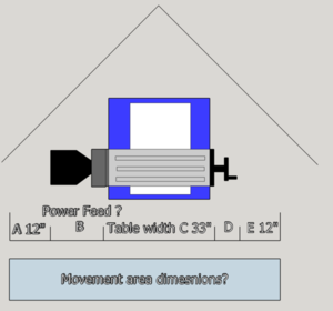
Check out my very rough diagram of the mill footprint, complete with misspelled labels:

Basically, from PM's given dimensions I know the table is 33" wide. It also has 23 or so inches travel, call it 24, represented by A and E, 12" each way. You can see also the way I plan to fit it in the corner.
The white block is the base and the blue is the chip tray.
The dimensions that would help me out with my design and placement would be:
-What is the actual dimension of the chip tray? (This will likely define the footprint of the stand)
-What do the power feed and hand wheel, B and D add to the width?
It would also be neat to know the dimensions of the base, and it would be killer to know the hole pattern as well, but the above dimensions are the most important.
It seems the power feed can be positioned far enough left and back that it almost touches the wall when full left. I bet if I just use the same dimension, or in other words use the B dimesion at D as well, for the handwheel, that would give me plenty of room to move right and still use the handwheel.
Can anyone tell me the dimensions of the tray, and B or D? Or the total width of the movement area dimension? Front to back is no issue, because the width will keep me from putting that far back in the corner.
Ideas? I'd also love to "see your stand" for your mill if you made one! I will be sure to post the construction of mine!

I posted an earlier thread asking for advice on which mill would suit my needs. I got really great information from the kind users here, and will order my mill soon.
One thing I'd like to do is begin work on the table for the mill, I think those stands that come with small mills are junk.
A better table affords better work surface and storage below.
I'm pretty good with designing and building, but of course I will be glad for any advice or tips.
My main issue here is to try to get some dimensions so I can move forward with the design or at least figure out placement.
Check out my very rough diagram of the mill footprint, complete with misspelled labels:

Basically, from PM's given dimensions I know the table is 33" wide. It also has 23 or so inches travel, call it 24, represented by A and E, 12" each way. You can see also the way I plan to fit it in the corner.
The white block is the base and the blue is the chip tray.
The dimensions that would help me out with my design and placement would be:
-What is the actual dimension of the chip tray? (This will likely define the footprint of the stand)
-What do the power feed and hand wheel, B and D add to the width?
It would also be neat to know the dimensions of the base, and it would be killer to know the hole pattern as well, but the above dimensions are the most important.
It seems the power feed can be positioned far enough left and back that it almost touches the wall when full left. I bet if I just use the same dimension, or in other words use the B dimesion at D as well, for the handwheel, that would give me plenty of room to move right and still use the handwheel.
Can anyone tell me the dimensions of the tray, and B or D? Or the total width of the movement area dimension? Front to back is no issue, because the width will keep me from putting that far back in the corner.
Ideas? I'd also love to "see your stand" for your mill if you made one! I will be sure to post the construction of mine!

