Question on carbide insert tip height

compact8

Registered
Registered
Joined
Oct 13, 2012
Messages
324
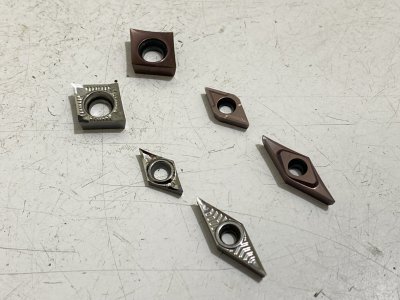
I have carbide inserts of three geometries : CCGT , DCGT and VBGT. For each geometry, I have got a type intended for cutting aluminum ( no coating ) and the other for cutting steel ( coated ). I found that the tips of the inserts for cutting aluminum are always lower by 0.1 mm or 4 thou compared with those for cutting steel. That makes me wonder if such difference is by design. Now I am not sure what to do. Should I use seperate tool bars for each type of insert ? My practice is to machine the shim for the tool bar to the right thickness and glue the shim onto the tool bar so that I don't have to shim it everytime.
 

Attachments

  • IMG_7471.jpg
    IMG_7471.jpg
    420.5 KB · Views: 7
Last edited:
Obviously you asking about a lathe, but it is helpful to mention that context.

Ideally you want the tip height right at centerline. But in practice 0.1mm is pretty close, and is only going to really matter on facing or parting cuts. The issue with being off centerline is that you are changing the angles (rake, clearance, etc). That change of angle runs as the inverse tangent of the distance off centerline vs the distance from the spindle center axis, so until you get close to the that center is doesn't have significant effect.
 
Most of the commonly used methods for setting tool height won't get you too much closer than .004". Just set your tools for the thicker inserts, letting the thinner ones run below center, not above.
 
I think if you turn a bar to 1 inch and then depth mic .500 down from top of bar too tool tip you can get closer then that.

Another way is to take a flat plate across lathe ways then take a height gage reading and check top of turned dia using that reading take 1/2 of that dia and you have true lathe center.
 

Attachments

  • 3AADFF54-3EE5-4911-BE84-5F2047506979.png
    3AADFF54-3EE5-4911-BE84-5F2047506979.png
    1.3 MB · Views: 15
I use the top of the compound slide as the datum and measure the height of center of rotation above it. Then the bottom of the DTI probe is set to zero the dial reading at that height and the height of the insert tip is measured. The accuracy is quite good. When the tip of the insert is measured to be 0.05 mm or 2 thou below the COR, I got a very tiny and visible bulge at the center after a facing cut. At 0.03 mm, I could not see the bulge but barely feel it with my finger nail. Anything less than that nothing can be seen or felt.
 

Attachments

  • IMG_7454.jpg
    IMG_7454.jpg
    345.8 KB · Views: 14
  • IMG_7453.jpg
    IMG_7453.jpg
    462.9 KB · Views: 14
  • IMG_7459.jpg
    IMG_7459.jpg
    424.3 KB · Views: 14
Last edited:
A dedicated tool height setting gage makes it fast. This one has a rare-earth magnet holding it firmly to the flat way.

WP_20200320_16_36_21_Pro.jpg
 
I line the insert to the tail stock live center; the tail stock is locked down when I set the height.
 
The tailstock center technique seems to be widely used, but I for the life of me, on my lathe, don't understand how that could even be close. I have a G0602 that I bought new, and the tail stock has to be about .020" too high. From what I have read, it's somewhat common as with wear it will slowly drop (slowly has got to be an understatement. As I want to be as close as possible, this would never do. I don't know how great my technique is, but I simply put a magnetic height gauge on the compound and set it on a tool that cleanly leave no nipple on the surface when facing. This is mt standard I use with the height gauge for all my tools. As for that tool that I use for the height on all, I start too LOW and slowly bring it up until that nipple is gone.
I plan on making a gauge like MrWhoopee as that seems easy and pretty darn accurate. My modified Winky's workshop parting tool (uses carbide) is the only exception as it runs about .005" higher than center as it is made to compress under load.
If your tail stock is too high by .020", you're going cut one heck of a taper.
The tail stock has to be concentric with the spindle axis.
 
It’s not .020”, lest than .010,more than .005 but I’m just saying, that won’t work on my lathe, probably many others. My understanding is, as I used to have that same concern, tailstock being high doesn’t have the same result as twist in the bed, doesn’t cause a taper as it’s not causing the tool to dig in further at one end or the other. Biggest issue would be using small drill bits. Tool being too high or low is a much bigger problem….at least for me.
 
Back
Top