Question on reducing how a beam bends under load

In keeping with most consumer devices like this...
...but considering your planning to add even more weight to it...

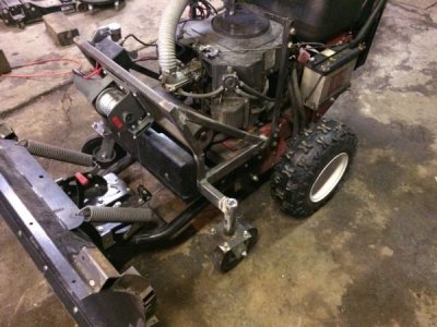
This is a 52" Snapper Pro Hydro walk behind commercial mower model, not a consumer model. I don't plan on adding anything more to this mower deck. I have made a plow attachment for this mower, but it uses a separate frame. The frame (and deck hanging from it) are unbolted from the drive unit, and a frame made specifically for the plow is bolted on. Here's a pic of the plow/frame attached to the drive unit(it's currently attached to the drive unit):
IMG_0996.jpg
 
We have an old saying "deeper is cheaper"
Yep--increase the moment of inertia. Think I-beam. Your angle iron idea is good, anything that increases the vertical height of the tube/member will reduce the tendency to deflect.
 
Yep--increase the moment of inertia. Think I-beam. Your angle iron idea is good, anything that increases the vertical height of the tube/member will reduce the tendency to deflect.
As ACHiPo mentions, increase the moment of inertia. For a rectangular section, the formula is "Base x Height cubed" or "B x H^3". Think of a 2 x 4 flat vs. on edge. Moment of inertia for 1 1/2" and 3 1/2" dimensions would be 11.8 in^4 for a flat 2 x 4, 64.3 in^4 for one on the edge or roughly 5.5 times stiffer on the edge.

Stress in a simply support beam is "sigma = (Moment x distance from the neutral axis) / Moment of inertia". So the bigger the moment of inertia, the less stress in the beam at a given load/torque.

Another formula (last one, been 39 years since I had my mechanics class in college) is "deflection = Force x Length / (cross section area x Young's modulus). Stress is force per unit area (head is starting to hurt . . .), so "deflection = stress x Length / Young's modulus". Young's modulus is a material property, use 30,000,000 psi for steel.

I'm sure more than anyone wants to know and I'm afraid to go further as it's been a long time since I had the class(es)! There are tables out there for the moment of inertia for a rectangular tube section; just plug in the wall thickness and OD's. Then do the "b x h^3" add on for your reinforcement and compare the ratios between the two. The 1/8" tubing with a piece of 1/4" stock of the same height welded vertically with just about double the stiffness of your beam (Two 1/8" thick vertical walls on the tube vs. an added on 1/4" wide bar of the same height). If you have the real estate to double the height of the add on, your make it stiffer by a factor of 8 (2 times taller ^3).

Bruce
 
The horizontal leg of a piece of angle iron will contribute little to stiffness in a horizontal plane. A piece of 3/16" x 3" or 4". flat stock welded to the vertical sides will stiffen your frame up considerably.
 
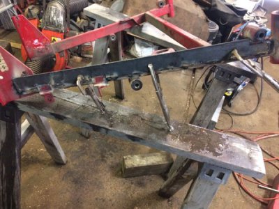
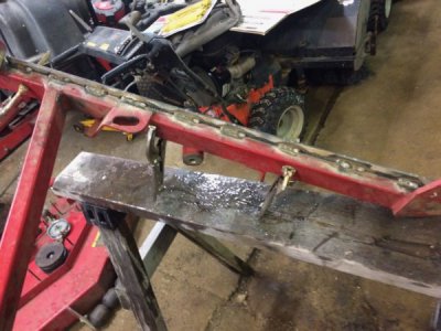
Welded on strips of 3/16 x 2, with some cutouts to go around existing bits on each leg.
IMG_1152.jpg
IMG_1153.jpg

One thing I forgot about was the mounting plate holes (the triangular piece on the end, that bolts to the main drive unit). The strip I welded on partially covered up that hole, and I didn't notice it until after everything was assembled and I was bolting it to the drive unit. Ground a small semi-circle for clearance and it's done.

Hopefully this works, as those two round bushings/mounts need to be located pretty precisely for the deck to stay level as it's raised/lowered, which I'm not particularly good at yet.
 
Welded on strips of 3/16 x 2, with some cutouts to go around existing bits on each leg.


One thing I forgot about was the mounting plate holes (the triangular piece on the end, that bolts to the main drive unit). The strip I welded on partially covered up that hole, and I didn't notice it until after everything was assembled and I was bolting it to the drive unit. Ground a small semi-circle for clearance and it's done.

Hopefully this works, as those two round bushings/mounts need to be located pretty precisely for the deck to stay level as it's raised/lowered, which I'm not particularly good at yet.
That'll do!
 
Back
Top