Quick Measurement Of Small Taper Angle

That is a lot of interesting data regarding tolerance standards...too much for this old guy though. I again find it interesting that we with home shops think we can chase tolerances that in reality we cannot even check. A grade B cheapo surface plate or non calibrated blocks that many of us own aren't capable of giving that accurate of measurement. certainly at least in a uncontrolled temperature environment. Measuring a existing taper, turning, bluing and possibly filing or sanding has always been the homeshop and even some job shops mode of making a satisfactory taper but then we are not held to ISO standards. If a morse taper for example seats, blues well and holds tight then it is good enough in my world. Making such a taper by my method would not possibly pass a qc inspection because a file or emery cloth automatically would cause a part to fail in concentric spec if nothing else. To make a ISO quality taper would require the part to be ground. You do not see commercially made ISO quality parts finished by turning, at least I haven't. Randy C has shown a often good enough example using 123 blocks. RJ Sakowski has shown the proper way using CAD. Both with far better explanations and a better grasp of trig than I have. If I had the need for a accurate measurement of a taper using Randy's second suggestion I would put the tapered part on a sine bar and put what I thought was a correct approximation of gage blocks under the bar. At that point I would use Randy's method of traversing the taper with a dti. If it read zero (unlikely) you would know the taper by using your gage block height to do the math. If it isn't zero then you would have to do the trig for the resulting difference. If I just needed to make a part to satisfy my needs I use Randy's method. If I were to need something more accurate RJ Sakowski's CAD and Tormach programs are the cats pajamas. But if I really needed that good of part and knew it had to meet the above tolerances, Hell I would just send it out to be ground. Thank you both for great descriptions.

Darrell
 
There are many, many ways to de-frock the kitty, right ? That's what makes this craft so fascinating. And there are not many activities that require inventiveness, precision, fine craftsmanship, patience, mathematics and the ability to explain to your wife why you need the next $500 worth of tooling.

(An old toolmaker once told me that if I could draw it, he could figure out a way to make it. I believed him) :)
 
....If I had the need for a accurate measurement of a taper using Randy's second suggestion I would put the tapered part on a sine bar and put what I thought was a correct approximation of gage blocks under the bar. At that point I would use Randy's method of traversing the taper with a dti...

That sounds good to me. The only problem might be securing the part to be measured so that its axis is aligned with the table travel.

However if one were very careful, misalignment could be accounted for by finding the "high spot" of each end of the taper using the "Y" axis movement and noting the "Y" travel. A bit of 3-D trig would be required to sort out the actual angle but as RJSakowski noted in an earlier post, it's simple enough to make a spreadsheet if repetitive solutions are required.

In fact this entire topic almost demands creation of a spreadsheet, ha-ha. Of course the elephant in the room is that measurement of tapers is not that important to the HSM - fit is the important characteristic.

I made a spreadsheet for mapping the errors on a well-worn lathe bed some time ago. Some day I might post it here, I think that it would invite interesting discussion :)
 
  • Like
Reactions: 18w
The bottom line, whether a hobbyist-machinist or a professional, is that the part meets the requirements of it designed task. I do not work to thousandths for much of what I do because that is not a requirement. I do not, for the most part, make parts for interchangeability; certainly not for my own use.

I like to look back at how medieval locks were made. A key was made first and the lock was made to fit. There is an old saying" carpenters work to inches, machinsts work to thousandths, blacksmiths work to snug." And yet when you look at some of the work done by blacksmiths (and locksmiths, silver and gold smiths) over the centuries, it is astounding in its fit and finish. Prior to Ely Whitney, every rifle that was made was unique in that you could not take a trigger from one rifle and replace that of another, etc. But those crude by modern standard rifles won a war and birthed a nation ( my apologies to any Brits out there; no offense intended).

When I make parts I invariably create a model and drawings and (try to) make them to print but if it is not to print I do not get bent out of shape as long as it meets my requirements. If it doesn't, I remake the part. You can make a lot of cool stuff without a metrology lab at your disposal.
 
Nah, I'm too dumb for all that spreadsheet 3d trig stuff. Hold the sinebar to a angleplate with a clamp or magnet and dial it in on the x axis, lay the tapered part on the sine bar against the protruding angle plate. I have seen sinebars with a groove and also ones with a side fence as well. But normally simply stand the part up and use the 123 block method. Easy peasy.

Darrell
 
There are many, many ways to de-frock the kitty, right ? That's what makes this craft so fascinating. And there are not many activities that require inventiveness, precision, fine craftsmanship, patience, mathematics and the ability to explain to your wife why you need the next $500 worth of tooling.

(An old toolmaker once told me that if I could draw it, he could figure out a way to make it. I believed him) :)
Randy, I think I know that machinist. He has a shop in Cupertino.

I sent this machinist a drawing for a tapered part, about an inch long and terminating with a .020" diameter, made out of Teflon. He sent me some parts almost by return mail. He told me he first experimented by making .020" Teflon noodles. He figured if he could make that, he could make our part. He is still doing so today. (Full disclosure, they are being made on a Swiss screw machine. I don't want to discourage anyone.)

He also made PEEK parts for us with a tolerance on one section of +.0002/-.0000. His technique is a trade secret. I happen to know how he did it but am sworn to secrecy, even internally in the company.
 
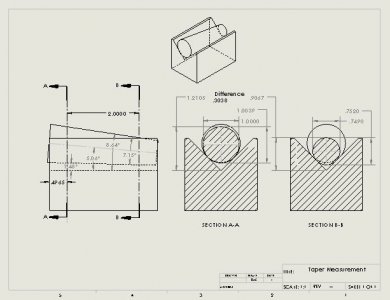
At two minutes to midnight, I came up with a simple solution to the problem posed in post #5 above. The difference in diameters in the taper, as outlined by Randy in post # 4 above is equal to .82843 times the measured difference in z . Divide that result by the the x distance between measurements and take the arctan to get the taper angle. Time for bed now. I'll post details of the calculation later. Suffice it to say, it works because the Vee block has an included angle of 90 degrees so the distance between the points of contact is equal to the distance between the vertex of the Vee block and the center of the circle.

THEN, I started to think about it, the vertical section is an ellipse. So my model in post #6 above is oversimplified as well. Oh well, back to the drawing board!

Update: This morning, I did it right and actually created models for the taper and block, created an assembly, and made a drawing of the assembly.
Taper Measurement.JPG
A few noteworthy items:
1. By comparing to the previous drawing, the taper angle is actually .05 degrees larger than predicted in the previous drawing.
2. Although the distance between the measurements is 2.0000 inches, the smaller diameter is .001" less than expected. This is caused by the fact that a taper is measured by a displacement along the taper axis but that axis is tilted by 5.06 degrees to the horizontal, making the axial distance longer by a factor of (1/cos(5.06)) degrees.
3. The difference between horizontal and vertical measurements of "diameters" is significant due to the fact that they are actually ellipses.
4. Finally, there is a .0020 difference between the actual difference in "diameters" and that predicted in post #5 above. That would seriously affect the taper angle determination.

So where do we stand? I have a sinking feeling that the determination of the vertical"diameter" will involve trig and furthermore it will require using the angle we are trying to measure as part of the measurement of that angle. Excel has a macro called solver that does a good job of solving math like this through an iterative process but this is really getting hairy in a hurry.

So plan B? Darrell as a good idea in post # 15 above. One problem is keeping the taper axis aligned properly, which Randy stated in post #6. One method, demonstrated by OxTool on YouTube is to move to x position 1 and scan back and forth with the y axis to high the high spot. Note the x, y, and z coordinates. Move to x position 2 and repeat. In Darrell's method he would build the gage block stack until the z axis difference is zero. To Randy's method, I would mount the taper in the mill vice so it rests on the horizontal and vertical surfaces of the vice. You still have to correct for the cosine effect (one two axes) but at least now you have known datums for reference. One thing that I like about Darrell's method is that the 5" span of a sine bar increases the accuracy of the measurement.

One last thought about the Vee block method. You can use it to compare an unkown taper to a known good taper; the difference measurements should be the same. Although it may be easier blue the taper and fit to a mating socket.

I wonder how the guys that make these tapers measure them?
 
....One method, demonstrated by OxTool on YouTube is to move to x position 1 and scan back and forth with the y axis to high the high spot. Note the x, y, and z coordinates. Move to x position 2 and repeat...

....However if one were very careful, misalignment could be accounted for by finding the "high spot" of each end of the taper using the "Y" axis movement and noting the "Y" travel. A bit of 3-D trig would be required to sort out the actual angle but as RJSakowski noted in an earlier post, it's simple enough to make a spreadsheet if repetitive solutions are required...

The defined points will locate a triangle that can be solved WHEN viewed perpendicular to the plane of the triangle but that angle isn't easily ascertainable from right triangle solutions because of the taper axial misalignment with table travel. That's why the 3-D trig was suggested.

I'm still thinking that this situation arises so rarely that the simplest solution is the best for me. (I would forget the more complex ones five minutes after reading them) :)

I expect that folks who make tapers in production use go/no-go gages that are calibrated by CMM. Of course if production is involved, many creative measuring solutions could be amortized into the cost. But that's really not something a HSM would encounter -
 
..Randy, I think I know that machinist. He has a shop in Cupertino...

If this was recent, I'd think it highly unlikely. I worked with the guy (at Zeta Laboratories in Santa Clara) around 1979 and he would have been middle-aged by then. He was German by the way and I'm embarrassed to say that I've forgotten his name.

There are a LOT of incredible toolmakers in the Bay Area but those that are worthy of the name using manual machinery are a slowly vanishing breed. When I worked at Westinghouse Marine Division in Sunnyvale (1965-1968) some of the stuff those guys turned out with manual machinery was on the verge of science fiction !
I'm aware that we were talking about two different people. The point that I was making, as you just did, is there are a good number of excellent machinists out there that can virtually work magic.
 
Back
Top