- Joined
- Apr 4, 2018
- Messages
- 53
There seemed to be a little interest in this conversion, and I didn't want to hijack Danny's thread, so I'll post a few pictures here.
A little back story... This all started when I built an anvil. I didn't really need an anvil, but I'd been watching some YouTubes on building anvils and you know how it goes.
Anyway, the top is mild steel and produces a thud (and a dent) when hit with a hammer. I figured I needed something a little harder on top. Not knowing anything about tool steel, I found a good deal on a piece of 1/2" X 3" D2 bar stock. It was only then I started educating myself on hardening, tempering and what it takes to "finish" a piece of tool steel. Naturally I had to built a hardening oven for this (which is a thread in itself).
So, now I have this oven for one piece of steel. What else can I do with it? Why, knives need to be hardened, why not try that! Looked into knife making and noticed everyone was using a 2 x 72 grinder. Oh gosh, I just might have to build one of those too.
I'd just picked up a load of scrap steel (you can never have enough), and started using what I had.
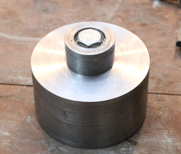
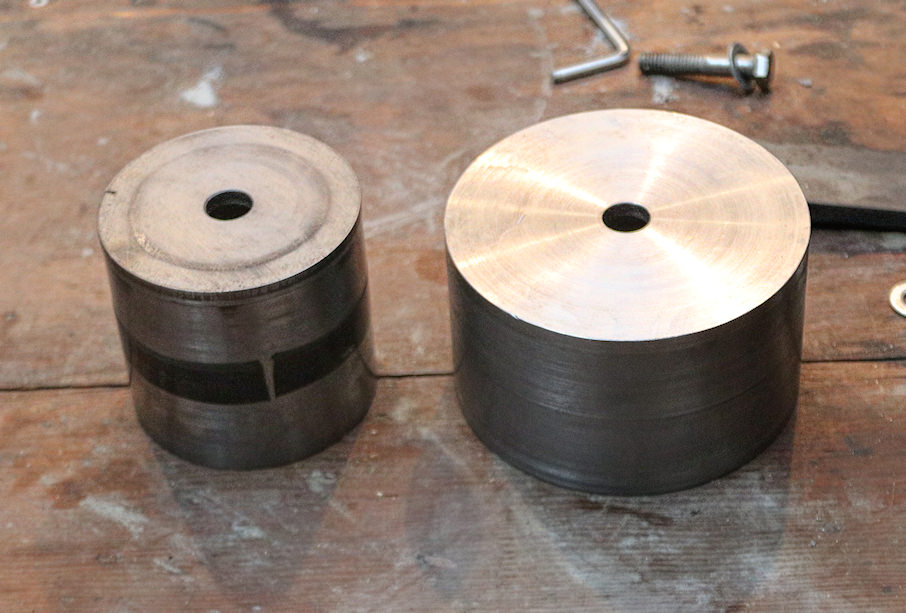
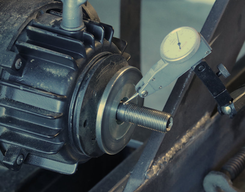
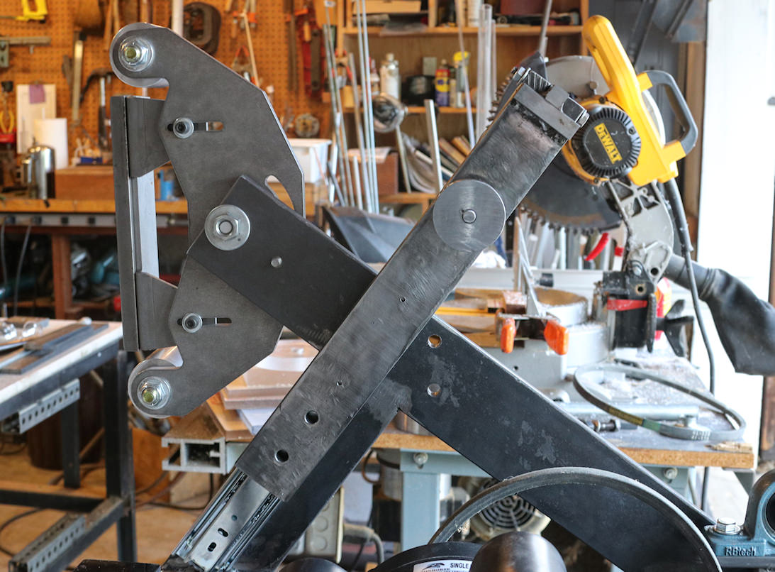
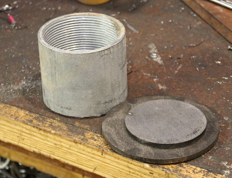
I bought the platen assembly from Oregon blade maker. I figured; why reinvent the wheel. For $100.00 you can't beat it. For the drive roller I first used a 3-1/2"steel conduit coupler (OD 4"). I machined and attach the two 1/4" discs, in the picture, which made a rabbet joint around the edge.
This one turned out to have some vibration, either from being unbalanced or poorly machined (most likely).
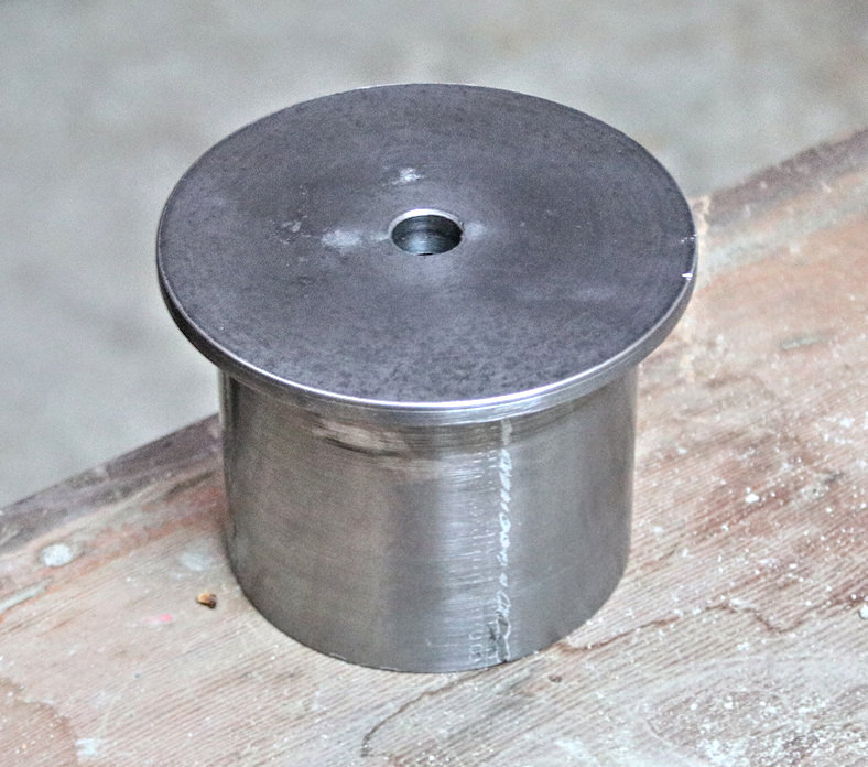
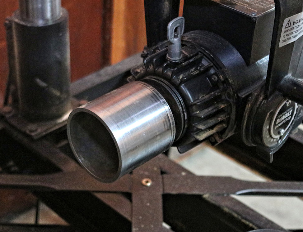
I just cut off a piece of 3" pipe for the next one. I happened to have a few 3.5" steel discs which fit perfectly on the end. This one went a lot better without a rabbet joint (unnecessary). I spot welded it on the inside to connect the two and then drilled the 5/8" hole on the lathe.
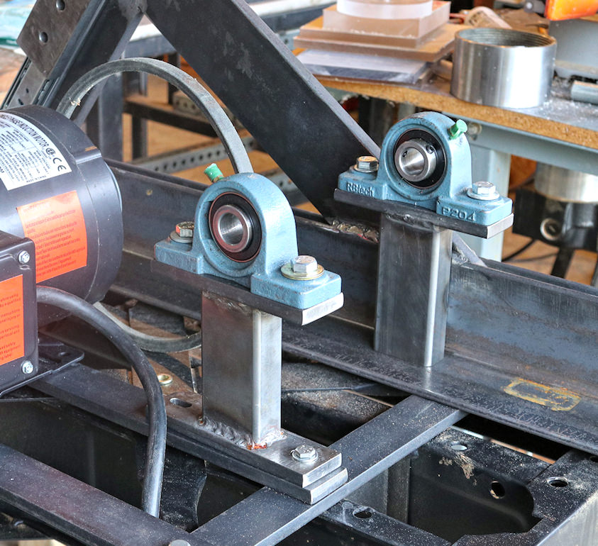
I sandwiched some large 1/2" bar stock between a couple of pieces of beefy angle iron to complete the frame. I also bolted a couple of pieces of smaller bar stock to the saw stand to provide a base.
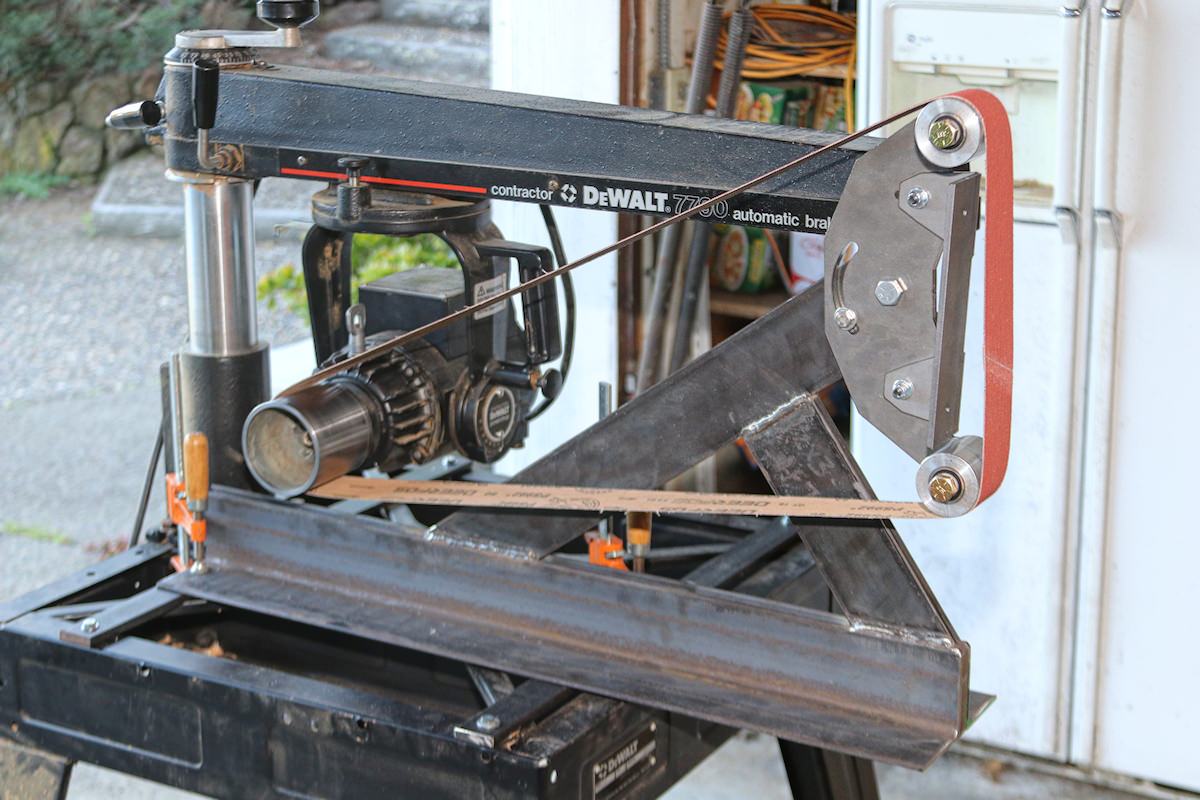
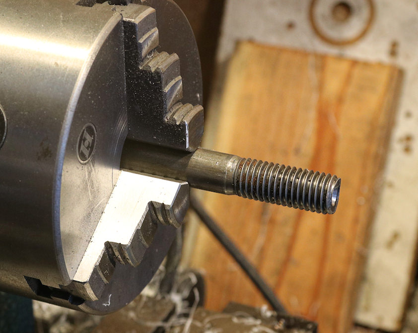
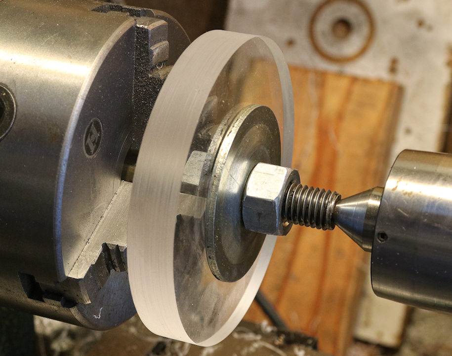
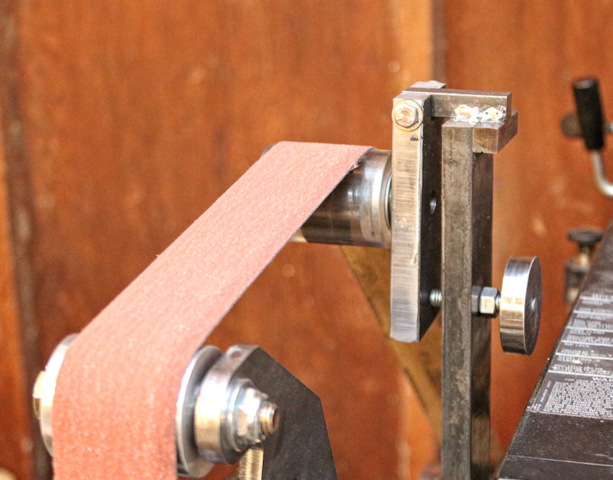
I then built a tracking arm and roller. I used a piece of 2" acrylic solid rod as the roller material. I machined a couple of 1/2" bearings into the ends and attached it with a bolt. I still couldn't get the belt to stay in one place, it kept wandering back and forth. So I put a piece of electrical tape around the center of the tracking roller and some on the drive roller. This helped a lot, but I'm going to try crowning those two rollers to get better tracking.
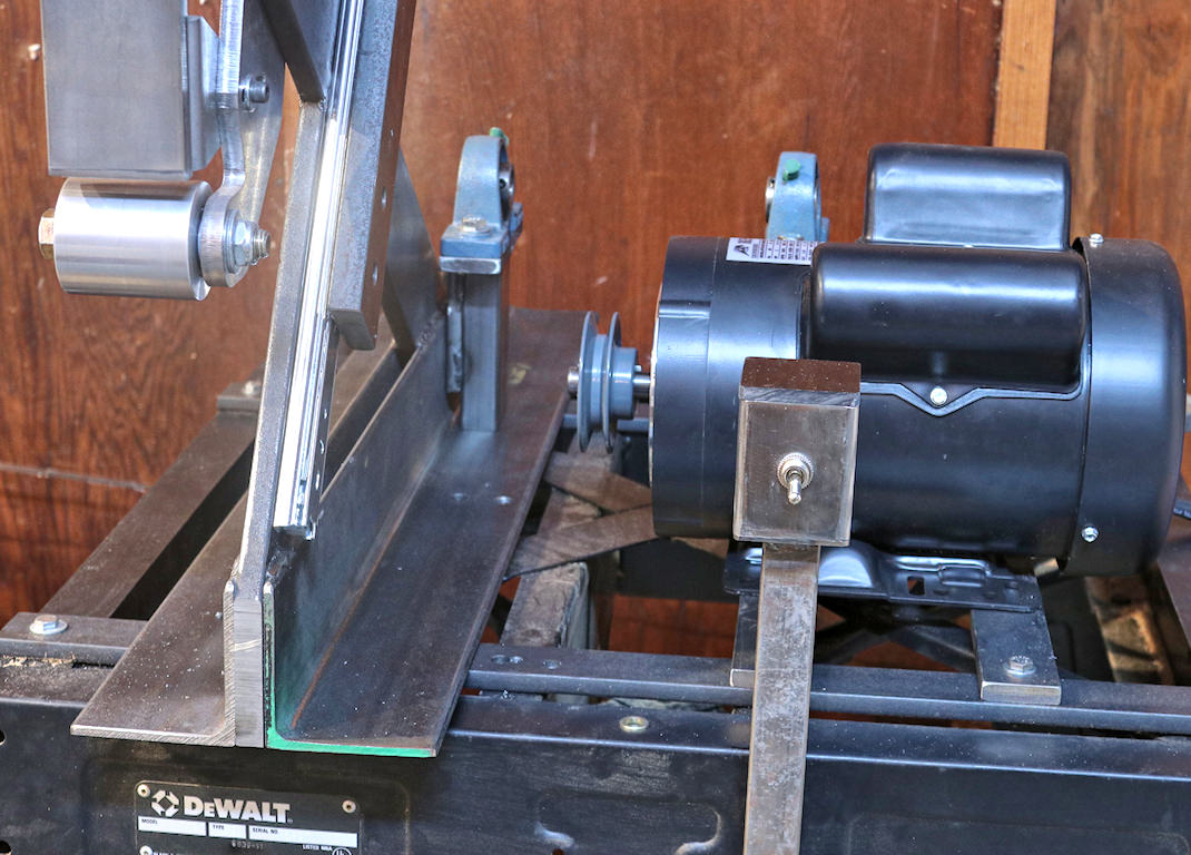
The belt speed is still a bit slow, so I got a coupling for some 4" pipe (4-3/4" OD) which I still need to assemble and machine for a larger drive roller. I've been eyeballing some VFDs on Ebay, but the recent projects have stretched the budget a bit, and the wife is not real happy about it. Since I'm just grinding steel, the bigger roller should be fine.
A nice feature of this grinder is being able to tighten and loosen the belt by sliding the motor back and forth on the rail. It has a screw lock to tighten it in place. It also has the on / off button right where you need it (don't have to build a control box).
Not the finest belt grinder, but then it only cost me about $150.00 to build.
Cheers,
Ted
A little back story... This all started when I built an anvil. I didn't really need an anvil, but I'd been watching some YouTubes on building anvils and you know how it goes.
Anyway, the top is mild steel and produces a thud (and a dent) when hit with a hammer. I figured I needed something a little harder on top. Not knowing anything about tool steel, I found a good deal on a piece of 1/2" X 3" D2 bar stock. It was only then I started educating myself on hardening, tempering and what it takes to "finish" a piece of tool steel. Naturally I had to built a hardening oven for this (which is a thread in itself).
So, now I have this oven for one piece of steel. What else can I do with it? Why, knives need to be hardened, why not try that! Looked into knife making and noticed everyone was using a 2 x 72 grinder. Oh gosh, I just might have to build one of those too.
I'd just picked up a load of scrap steel (you can never have enough), and started using what I had.
I bought the platen assembly from Oregon blade maker. I figured; why reinvent the wheel. For $100.00 you can't beat it. For the drive roller I first used a 3-1/2"steel conduit coupler (OD 4"). I machined and attach the two 1/4" discs, in the picture, which made a rabbet joint around the edge.
This one turned out to have some vibration, either from being unbalanced or poorly machined (most likely).
I just cut off a piece of 3" pipe for the next one. I happened to have a few 3.5" steel discs which fit perfectly on the end. This one went a lot better without a rabbet joint (unnecessary). I spot welded it on the inside to connect the two and then drilled the 5/8" hole on the lathe.
I sandwiched some large 1/2" bar stock between a couple of pieces of beefy angle iron to complete the frame. I also bolted a couple of pieces of smaller bar stock to the saw stand to provide a base.
I then built a tracking arm and roller. I used a piece of 2" acrylic solid rod as the roller material. I machined a couple of 1/2" bearings into the ends and attached it with a bolt. I still couldn't get the belt to stay in one place, it kept wandering back and forth. So I put a piece of electrical tape around the center of the tracking roller and some on the drive roller. This helped a lot, but I'm going to try crowning those two rollers to get better tracking.
The belt speed is still a bit slow, so I got a coupling for some 4" pipe (4-3/4" OD) which I still need to assemble and machine for a larger drive roller. I've been eyeballing some VFDs on Ebay, but the recent projects have stretched the budget a bit, and the wife is not real happy about it. Since I'm just grinding steel, the bigger roller should be fine.
A nice feature of this grinder is being able to tighten and loosen the belt by sliding the motor back and forth on the rail. It has a screw lock to tighten it in place. It also has the on / off button right where you need it (don't have to build a control box).
Not the finest belt grinder, but then it only cost me about $150.00 to build.
Cheers,
Ted