- Joined
- Feb 2, 2014
- Messages
- 1,059
I have started another engine build I but couldn't decide what to call it and as it will be painted red then I might as well call it that.
This project started because I was thinking about a ball bearing crankshaft and connecting rod. All ball bearings so I started messing around and came up with a design to try with a 1 1/2" throw.
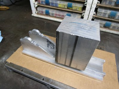
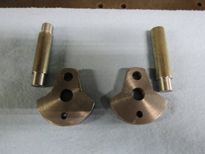
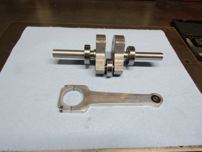
This shows the two webs and the outer shafts.
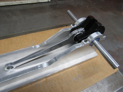
Since I didn't have engine in mind I just made a rather short 5" connecting rod to go with it.
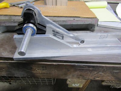
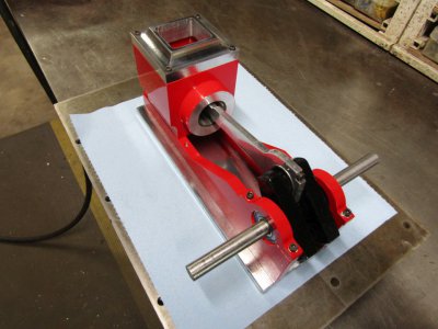
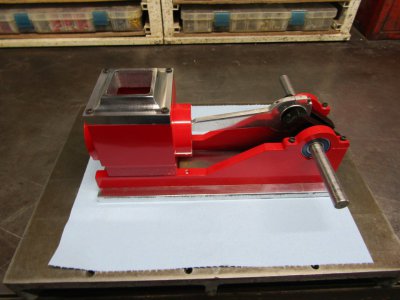
Here it is assembled and ready for paint.
It did turn out quite well so I decided to make an engine to go around it but that didn't happen.
"Royal Blue" is an engine I had built previously and there is a build thread on this forum if you are interested. That "Hit Miss" engine is a nice slow runner with several revolutions between firings so how would a similar engine with a longer stroke perform?
As I was looking over Royal Blue and thinking about what supplies I had in stock when it struck me.
Royal Blue already has a 1 1/2" stroke. No reason to build another engine with the only difference being a ball bearing crank and connecting rod. So back to the drawing board and I came up with A 2" stroke crankshaft.
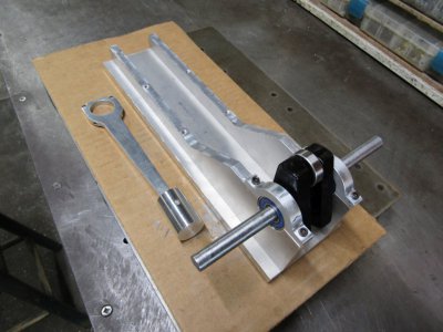
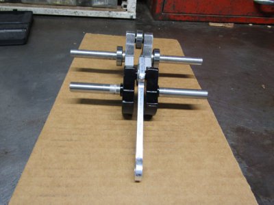
This shows the two cranks together with the 2" model in the rear.
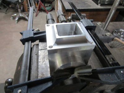
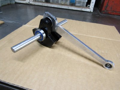
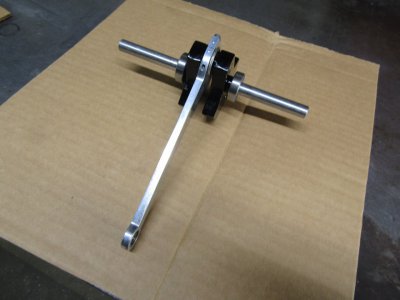
I made a crude drawing to see where I might run into interference problems. I did not want to increase the 1" bore so this engine will have to be longer with the cylinder further away from the crank in order to get room for the rod. After several sketches it looks like a 7" long connecting rod that should work and here it is all painted and ready.
More to come
Thanks for looking
Ray
This project started because I was thinking about a ball bearing crankshaft and connecting rod. All ball bearings so I started messing around and came up with a design to try with a 1 1/2" throw.
This shows the two webs and the outer shafts.

Since I didn't have engine in mind I just made a rather short 5" connecting rod to go with it.
Here it is assembled and ready for paint.

It did turn out quite well so I decided to make an engine to go around it but that didn't happen.
"Royal Blue" is an engine I had built previously and there is a build thread on this forum if you are interested. That "Hit Miss" engine is a nice slow runner with several revolutions between firings so how would a similar engine with a longer stroke perform?
As I was looking over Royal Blue and thinking about what supplies I had in stock when it struck me.
Royal Blue already has a 1 1/2" stroke. No reason to build another engine with the only difference being a ball bearing crank and connecting rod. So back to the drawing board and I came up with A 2" stroke crankshaft.
This shows the two cranks together with the 2" model in the rear.

I made a crude drawing to see where I might run into interference problems. I did not want to increase the 1" bore so this engine will have to be longer with the cylinder further away from the crank in order to get room for the rod. After several sketches it looks like a 7" long connecting rod that should work and here it is all painted and ready.


More to come
Thanks for looking
Ray


