Reducing speed on AC single phase motor

TORQUIN

Registered
Registered
Joined
Mar 19, 2015
Messages
154
I have a Walker Turner band saw with 2 speed gear box as it is wood and metal capable. It has a 1725 single phase, 120V, 1/2HP motor on it. From what I have been able to gather, this is not the original configuration, as it should have come with a 3 phase motor that turned somewhere around 1100 RPM. Since, at the lowest speed, it's still a bit fast for metal, I am researching my options for slowing the motor down. I AM using it to cut metal now, with a bi-metal blade, and not having any issues, but I am thinking I should slow it down if I can do so economically.

The possibilities I know of include:
Rheostat, not a good option because of the reduction in voltage lowering torque too much. Also, it may kick in the startup circuit.
VFD: I have a 4KW VFD sitting on a shelve, but I do not know if its output can be single phase and I may get the startup circuit problem.
Change the motor over to 3 phase and use the VFD: This seams possible, with my limited knowledge. Can I just remove the start capacitor and go around the startup circuit and run the single phase motor as a 3 phase motor?

Ideas and advice appreciated.

Thanks,
Chris
 
I'm not familiar with your particular saw, but on many of these saws with a two speed gear box, the gear box is driven via V-belt from the motor. If this is how your saw works, have you given any thought to changing the size of the drive pulley on the motor or the driven pulley at the gear box or both ? (eg; reduce the diameter of the drive pulley or increase the size of the driven pulley}.
Just some food for thought.

Ted
 
Single phase and 3 phase motors are very different (cannot bypass the capacitor and run it like 3 phase - not even a little bit).

That single phase motor (1725 rpm), needs to run above about 1600 rpm, or else the centrifugal switch will kick the start winding in. You may have noticed that when you overload a single phase motor (bog it down) you can get the start switch to kick in. The start windings are not designed for continuous use - the motor will burn out. The rheostat is a no go (does nothing related to running speed, it just reduces the voltage, resulting in less current, which means less power so slower running, start switch kick in -- - - all bad things).

You may be able to run that single phase motor faster - with a 120V VFD (only using 2 legs off the drive). I've never tried that, but it would be interesting to hear from anyone who has. You just have to keep the frequency over about 55 Hz (bump that up if the start winding kicks in) - then you should be able to over clock to 90 Hz (perhaps even 120Hz). Thus to make it variable, you would need to do as "talvare" points out - change pullies to get a lower base speed.

Let us know how you make out.
 
Another option may be to go to a smaller pulley on the motor, a larger pulley on the gearbox, or both.
Richard
 
Another option is a 6 pole motor (110v single phase) . Their normal run speed is 1140 rpm.
 
You cannot use a standard VFD on a single phase motor, there are some "single phase" VFD's but they expensive and will not have the performance of a standard 3 phase motor/VFD. If you have a 4kW VFD, you could pick up a 3 phase 2 or 3 Hp motor for not much and get a much wider speed range with good performance. Alternative would be as mentioned which would be to change the belt ratios. If going with a 3 phase motor, you might consider a 1200 RPM motor 1.5HP or 2HP 1750 RPM, you can over-speed it to 90Hz and probably run it down to 20 Hz with decent performance. You might also check Craigslist, you can often pick up something inexpensive.
 
A 1725 rpm @ 60 hz induction motor will run at 1440 rpm on 50 hz. Many motors are rated for dual frequency. At 40 hz, the motor would run at 1140 rpm. The two questions that come to mind are what is the minimum rpm at which the centrifugal switch kicks in and what are the effects of the decreased inductance at the lower frequency.

I have been seeing an increased number of VFD intended for use on single phase motors. It seems that the most common application is for fan and blower motors. In such an application, the required torque decreases with rpm. (IIRC, it is an inverse square relationship) For shich a use a reduction in motor torque is inconsequential. For most of the applications we might have, low end torque is an important feature and that might pose a problem.

Some of the videos that I have seen modify the start circuit by bypassing the centrifugal switch and using the start winding as a second phase. Others use the motor as is, presumably not operating in the region where the switch is activated. The trip point for the start switch can be modified by changing the fly weights or the spring force or both. Adding mass to the fly weights or decreasing the spring force, the trip point can be lowered. An induction motor with a defective start circuit can be started by manually rotating the shaft. A little nudge in the right direction will get the motor running so rotational speeds as low as 50 to 100 rpm will start a motor.

As I understand it, the more sophisticated single phase VFD's use the start winding as an auxiliary winding , modifying the current and phase to provide for motor reversal and to control heating.
 
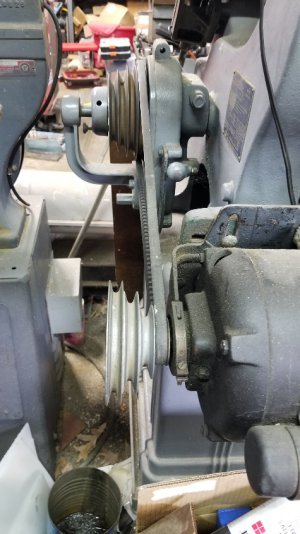
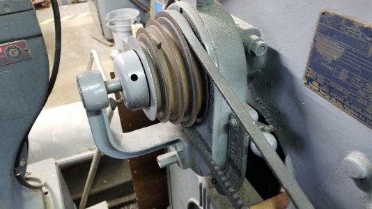
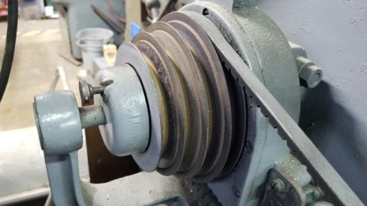
I looked at the pulleys, but not as far as removing the wheel pulley to see what's going on with the gear change mechanism. I figured I'd research the electrical end first.
2020-10-27 10.54.45-33.jpg

2020-10-27 10.54.58-33.jpg

2020-10-27 10.55.29-33.jpg

Unless I put a stepped idler in the middle, I don't currently see a way with the pulleys. Not that it can't be done, but can it be done for a reasonable cost and time frame.


Thanks,
Chris
 
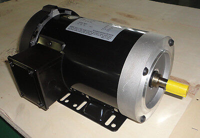
Although I like the idea of a larger motor like mksj suggests I suspect your pulley is a 5/8" bore so you are probably limited to a 56 frame motor with a 5/8" shaft. I think they typically top out at 1 hp. Here is a 1hp. I would prefer a TEFC (totally enclosed fan cooled) rather than this ODP (open drip proof). This is a 3 phase 1200 rpm motor.

 
OK, I must of missed the motor Hp, thought it was 1.5 and I see it is 0.5. So a 1-1.5Hp motor would be ideal, and give you similar Hp at 20-30Hz. Below is a 56 frame 1.5 Hp with a 5/8" shaft that is supposedly inverter rated. Not worth using the current motor, even if you could reduce the speed with a single phase VFD the performance would probably be poor.

 
Back
Top