Repairing a 25x100 binocular

savarin

Active User
H-M Supporter Gold Member
Joined
Aug 22, 2012
Messages
4,101
A couple of years ago my 25x100 binocular fell out the back of a truck (fell out not fell off the back of) and broke in half.
A club member had a go at welding the little broken pieces back together but unfortunately not very well.
I was just going to keep then as individual finder scopes for my giant binocular (when I get back to making it) but yesterday I felt like a break from the powder coating oven and decided to see if I could repair them.
I had disassembled them two or more years ago so cant remember exactly how they go back together.
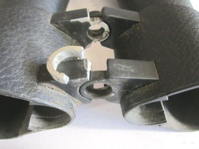
25x100-1.jpg

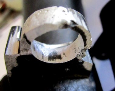
This is the broken ring
25x100-2.jpg

This is the repaired ring that doesnt look as if it will last very long
25x100-3.jpg

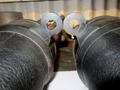
The fixing holes at the wide end are oval for some reason, I can only think that the two tubes do not move entirely parallel with each other and this is for clearance but I dont know for sure.
25x100-4.jpg

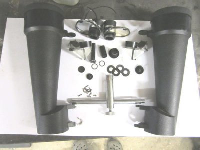
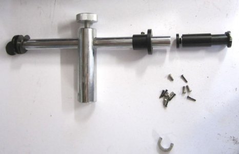
After some experimentation it looks as if all the parts go together like this.
The small screws are to hold the prisms in the housing.
25x100-5.jpg

I think there is sufficient material to allow two new side plates to be screwed to the broken originals so I'm making a mandrel to pass through all four fixing rings to spot the centres of the new plates.
I will bore these to size as all four are slightly different diameters as the main fixing pin is tapered.
The spacer will then have to be shortened to fit in between them also.
I hope I can get them close enough to original as re-aligning the optical assemblies will be a difficult one.
Translation - I've never done this before.
 
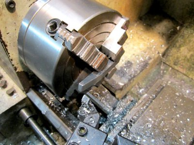
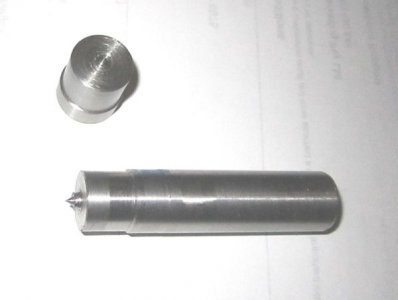
Made the two different transfer punches to mark the centres (not a mandrel as I said previously)
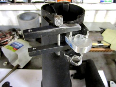
Started one side plate and filed it to shape then realised I would need a clamp of some type to hold it tight to the remains.
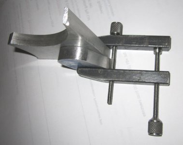
So today was just a quick and dirty toolmakers clamp.
Tapered the ends like this.
25x100-6.jpg

Only managed to make one screw though but it looks like it will work well.
25x100-7.jpg
 
Its difficult to progress when your neighbor pops round to share a beer and stays for the afternoon.
A good time was had by all but I did manage to finish the other screw for the clamp.
25x100-9.jpg
heres a shot of the transfer punches I made earlier but forgot to photograph.
25x100-8.jpg
 
Are the broken parts screwed from the inside ? Why not remove them and make yours where they are? Should be strong enough.
 
Unfortunately the whole tubing is a cast module in what I assume is a zinc alloy from the look and the way it drilled. I was contemplating filing the mounting blocks off flat and screwing the new ones on from the inside but decided it was way too much work.
(read too difficult for me)
Yesterday I bored the first one and screwed it into place, semi assembled the two halves and it moved smoothly through its travel with no twisting or play so I have high hopes.
 
Gee, I've never taken something apart and then left the parts just sitting on a shelf for a couple of years. HA! I have several boxes with disassembled parts in them. :eek:
Try to keep it all collimated. Otherwise you end up looking in two different directions at the same time. Crosseyed or at least with a headache after a couple of minutes
of viewing. :confused:
Do you know what make and model it is? Very fortunate that it was the case that broke and not any of the optics.

CHuck the grumpy old guy
 
It looks like the optics didnt fair as well as I'd hoped, one of the eyepiece focusser units is also damaged. I need to get a good set of jewelers screw drivers for them.
I have two more damaged binoculars sitting here, a 25/40 x 100 Oberwerk and a bushnell 10x50.
The Oberwerk were given to me because they had taken a dive and smashed the lens hood and bent the casing making it impossible to unscrew the objectives.
I cut the damaged hood off and re-aligned the optics and they work well but are way too heavy for serious astronomy work.
The Bushnells are a mates that are so far out of alignment that its impossible to look through one side.
It looks like I may have found a small business if I can get them all working.
 
Just send the Overworks to me and I will use them astronomically. I'm just starting to build a heavy duty parallelogram adjustable height binocular
stand for just this type of binocular i.e. BIG and heavy. I love binocular astro viewing and spend a lot of time stretched out in my camping "chaise lounge"chair
sweeping the Milky Way for faint fuzzies whenever I can. A cooler of cold beer next to me, the stars above me, it doesn't get much better for an old coot like me.

CHuck the grumpy old guy
 
Well worth doing Chuck.
Have you thought of mounting the chair on a turntable?
Some small castors and two sheets of ply and voila.
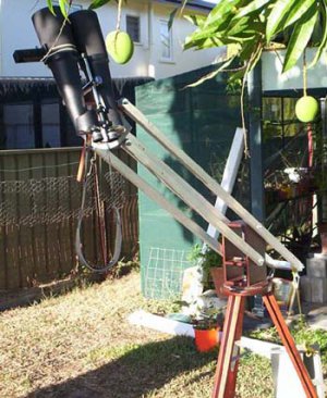
I built a parallelogram mount for the 25x100 some years back around 2005.
I loved using it and at public gatherings it was brilliant and an extremely stable a viewing platform.
I could find the object then lower them for the kids to see without loosing the object.
I took the design from a book on building telescopes but cant remember the title.
This was well pre lathe time.
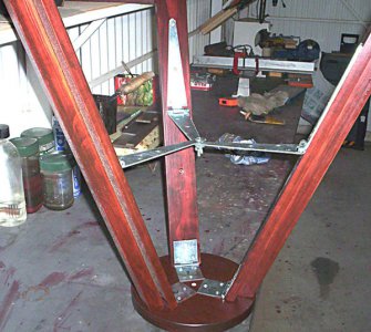
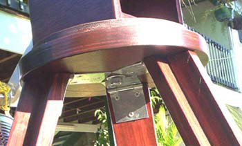
The tripod was made from standard pine section glued and screwed to form
a "T" section and held to the top with three hinges, three gate hinges made the spreader/brace.
The central bolt was captive to one hinge and I kept a few wing nuts in the bag for the inevitable field loss at night.
hinges-1.jpg

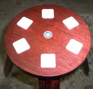
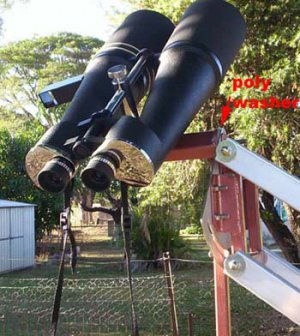
The top was a disk cut from two layers of ply pinned and glued with teflon squares pinned with small panel pins and glue. The heads were set below the surface.
topL.jpg
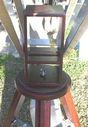
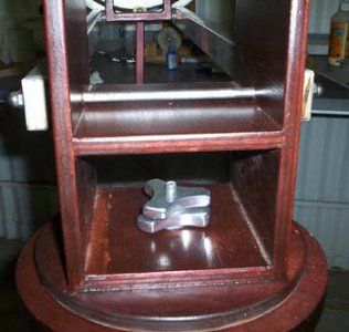
The swivel box was made from ply with a central spreader pinned and glued to a circle of ply with the good old ebony star formica sheet "A la John Dobson"
centre boxL.jpg
The locking nuts were cut from 10mm aluminium plate and threaded.
Unfortunately this was not a brilliant success as they did unscrew . I will be fabricating a type of clutch system like I have on the refractor to replace this.
The parallel arms are light weight box section aluminium extrusions with plywood inserts so the bolt pressures wont crush them.
The pivots are just some mild steel rod with threaded ends. I will replace these with stainless in the refurb.

locknutsL.jpg
the view from underneath
underneathL.jpg

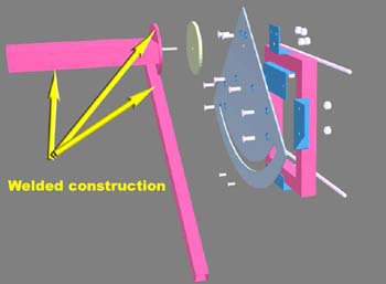
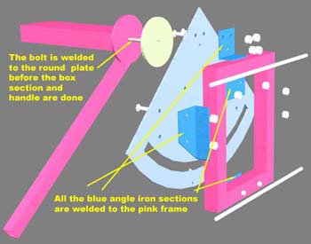
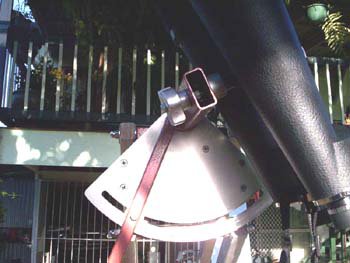
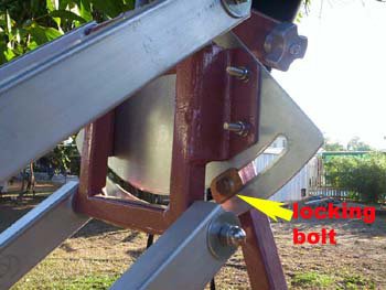
To hold the binos I made a locking quadrant
explodeFrontL.jpg
explodeRearLjpg.jpg

quadrantL.jpg
The thumb nut needs replacing with a new version made in the lathe for a smoother action and locking/unlocking
QlockL.jpg

frontL.jpg
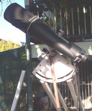
The extended dew shields are black card and just slip over the original hoods and the rigel quick view is held on with two elastic bands.
shieldsL.jpg

Note how the rear end is short as I didnt want a long extension swinging around in the dark smacking into other people.
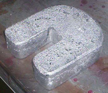
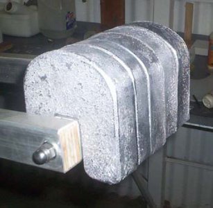
This necessitated to use of a heavy counter weight and rather than carry around a concrete block I cast a set of lead weights.
overviewL.jpg

weightL.jpg weightsL.jpg
They sat nicely in place on the end cross member and never moved irrespective of the angles.
Being individual weights it was easy to set them up.
The whole setup was very user friendly and made using the binos an absolute pleasure.
So
I made and extension for the weights and a stronger head to hold the oberwerks.
Bad move, with the huge weight of the oberwerks and the extra lead plus the extensions produced so much inertia that they were horrible to use.
I need to re visit them and see if a 45' diagonal can be fitted so I can use them to see the sky.
Initial quick experiments seem to indicate this will not be an easy thing to do.
 
Back
Top