-
Welcome back Guest! Did you know you can mentor other members here at H-M? If not, please check out our Relaunch of Hobby Machinist Mentoring Program!
You are using an out of date browser. It may not display this or other websites correctly.
You should upgrade or use an alternative browser.
You should upgrade or use an alternative browser.
Repouring a Babbitt bearing headstock
- Thread starter Privateer
- Start date
- Joined
- Jul 9, 2014
- Messages
- 613
I suspect that the cast iron casings were machined on a vertical borer whiles the casing was being rough machined with the bearing caps in place.
Then on removing the caps the casing was reheated to allow it to normalize from the developed stresses , whilst it was it was starting to cool at the relevant temperature a thin wide bar of white metal was pressed into the seat and into the cap seat then as separate items , then the casing was left to cool or was controlled cooled to a handable temp by oil quenching.
This would leave the rough bearings well adhered to the cast iron . the ends of the bearings would then be milled off and the cap bolted to the shaft to be milled and reamered to the final required shaft sizes. Most white ( Babbitt's metal bearings do have some self lubrication quality .
In my apprenticeship I had to use a drag & cope arrangement using a green sand core to individually cast a bearing to the end of the main wheel rod of an old military use steam engine this was an Engineering Apprentice exercise only , the engine was long gone .
The bearing was a mere 1/4" thick once it had been shaped down to side thrust dimensions, bored & scraped to an engineering fit using hand tools & a simple jig only . It's near 50 years ago but I seem to recall that you could cast to almost 1/2 " and inch providing you used hot ashes and hot sand banked about a foot thick around the filled mould to slow down the mould 's cooling rate cool
My thoughts for your bearings are :-
Can you locate an engineering company who makes bespoke white metal lined steel shell bearings out of a manufactured sheet that you see on todays modern vehicles They are available in a mind boggling range and some ( the bigger ones ? ) can even be rolled down to a specified thickness and shaped to a required diameter .. their fit would be better , you could " notch " the cap and the main seat just like it is done on a vehicle engine's crankshaft to stop the bearing rotating and use some of the one ounce glass oiler pots to visually see that you have oil a ready for your bearings .
Another route you could think of using is that of a rail enthusiasts group who rebuild the old timers steam engines in time honoured methods .. perhaps they will have an annealing oven in which you could heat the whole bare bones cast iron casing ready to accept strips of rolled down to almost thickness white metal to be pressed in to the cup and seat . They should have some sort of vertical borer to allow you to correctly mill and ream the bearings in the correct alignment using the one of the stock casting faces that have been precision ground at the production stage as the reference point for alignment .
If you really want o play and aren't too worried as to whether it works first time you can also make an annealing oven yourself using several old cut open steel oil drums to make a four sided box and a lift off lid.
Build a big charcoal fire in it to get a bed of red & white hot ash about a foot deep and place the casting at least six inches above the heat once the ash bed is fully developed , cover , and leave for twelve hours so the casting gets to dark ( barely ) red then try laying in a pre made & cut to rough dimensions strip of bearing metal & clamping it in place using an 1/8" undersized turned shaft .
I'd have a play with some other scrap cast iron casing first , use a pyrometer to get the adhesion temps & white metal melting point exactly right so you don't melt everything .
Hmmmmm ! Melt everything ????? .
Perhaps with a pre heated casting done as above , have a bolt on through the middle shoe/half saucer set that seals to either side to the to the casing use high silicone rubber sealer to seal it. have a silicone covering over the clamping bolts so they can be pulled free or if of a full thread bolt.. can be un screwed when every thing is cold to remove the bearing forms . Fill the whole bearing cavity solid including the space for side /end thrust surfaces .....do same with bearing caps then when well cool and handable with bear hands remove the forms 7 start your milling and scraping marathon.
In 1974 I helped stoke an annealing oven out in Cyprus , for 18 hrs so we could preheat to weld a 1/2 ton cast iron gear box casing that had thrown a bearing and shaft out the side . It worked well and is like as not still out there at work on the island .
- Joined
- Aug 23, 2014
- Messages
- 216
some interesting info, cheers. the automotive style(or something along those lines) bearing conversion is the way i'm leaning at this stage, to keep surface finish quality rather than high RPM.
trying to stay away from repouring/foundry type stuff myself and i think if there was anyone around here who could repour for me, it would likely cost an arm and leg.
if the headstock is rough machined before the babbitt is applied, that's ideal. i wasn't sure whether a bearing like that would be poured onto unmachined bore(providing a better keying surface?) or not.
machined surface would mean i could knock out the babbitt metal and turn up some sleeve bearings
to suit. hew:
hew:
another thought that i have had was skimming and shrinking a sleeve onto the spindle, then boring the existing bearing to suit, but that would be dependant on how much material could be safely removed.
at the end of the day, i'm not in a position to go by trial and error, if i mess it up, i bin the lathe.
trying to stay away from repouring/foundry type stuff myself and i think if there was anyone around here who could repour for me, it would likely cost an arm and leg.
if the headstock is rough machined before the babbitt is applied, that's ideal. i wasn't sure whether a bearing like that would be poured onto unmachined bore(providing a better keying surface?) or not.
machined surface would mean i could knock out the babbitt metal and turn up some sleeve bearings
to suit.
another thought that i have had was skimming and shrinking a sleeve onto the spindle, then boring the existing bearing to suit, but that would be dependant on how much material could be safely removed.
at the end of the day, i'm not in a position to go by trial and error, if i mess it up, i bin the lathe.
Last edited:
- Joined
- Aug 23, 2014
- Messages
- 216
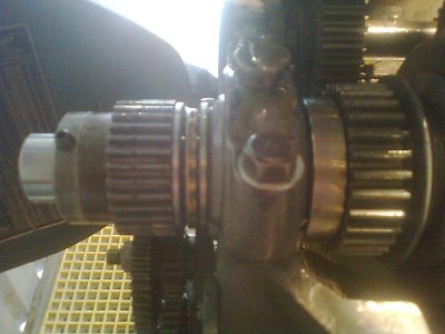
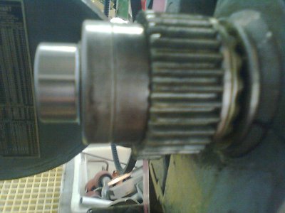
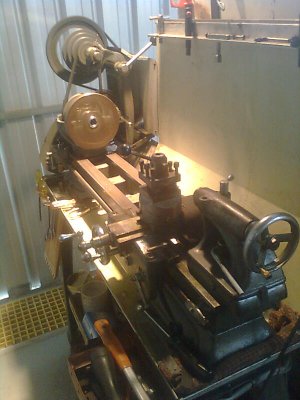
It's been a while, finally went with making up a new spindle from 4140. Found that the babbitt had no discernible wear, roughed out a spindle and had the final cuts done by cnc. Works a treat. A few alterations to improve on the original. Have managed to get it cutting 4140 @ 3"/3.5"dia, .050" doc, .005" feed, needless to say, "happy as a pig in poop".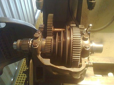


As Michael said. The article appeared in Jan/Feb 1983 issue of Fine Woodworking. Written by Bob Johnson who "...restores vintage woodworking machinery..." as the footnote says. Good reading, highly recomended before you start your project. Can send you a PDF if you like.If you have a woodworker friend who has back issues of Fine Woodworking, They had an excellent 3 or 4 page article on re pouring babbit bearings. The article was in the early 80's - back when they were a serious magazine. I can look up the issue if you like.
Michael
- Joined
- Aug 23, 2014
- Messages
- 216
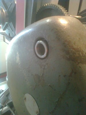
It is. I left all that to the guy that did the final turning on a cnc machine. Same as original until you get to the left end, swapped outboard collar to the other side of the 32 tooth gear and put another bearing in its place as per inboard side of left journal. The bit at the end extends just through the change gear cover to keep crap out of the gears.
- Joined
- Aug 12, 2014
- Messages
- 269
Why not?.OK. But without it being threaded to the end, you can't attach a collet closer or spider.
John.
- Joined
- Aug 23, 2014
- Messages
- 216
Collet closer, don't have or need one. Spider, i can put set screws through the spindle extension. And the original spindle would have had to have the nut removed to do either as the thread didn't reach past the nut, actually a full thread back inside it.

