- Joined
- Oct 25, 2014
- Messages
- 35
I have re-assembled my grandfather's old South Bend lathe and now I am trying to wire up the motor. After a bit of reasurch, my dad and I figured out that it is an old Repulsion start - Induction run motor that can run on 110 or 220, single phase. Unfortunately, the wires were hacked off with only about 2" or so outside the case, though 2 of the wires are connected together (of the 4). I belive that the motor was set up to run on 220 (I don't remember, but my uncle does), so I want to stick with that. Right now I simply want to wire up the motor and see if it will run. There are a couple of motor shops here in the area and pretty much the response has been to the tune of: "that motor is to old - none of us know anything about it," "it has sleave bearings that have to be oiled," "we can get you a great price on a new motor...." In their defence, I only showed pictures as the motor is simply to heavy to lug around easily. While I'm not set on the fact that I HAVE to use this motor, I just simply want to see if it will run, and considering the fact that all, but one, of my motors has sleave bearings/needs to be oiled, that isn't a problem for me.
So, the motor turns over freely by hand. I did pull off the 'back end' (non-output shaft end) to vaccuum out a little bit of gunk and to look at the wires and brushes (they look fine actually). I also checked the wires going through the case and did ohm out the wires to make sure I don't have any obvious shorts.
My question is how would I wire up the motor to test it? The 220v outlet I have avalible is the 4-prong style used for a dryer. I have 4 wires - red, green, white and black. I know that green is ground (I know this is temporary, but I still want to have the motor grounded!), white is neutral, but what do I do with the red and black. How do I get from the 3 wires (red, black and white) to the 2 on the motor? The motor leads have no differeing colors that I was able to see (I did check).
I also have a simple toggle switch (from ACE) that is intended for machinery motors rated at 100-240v and up to 30 amps. I don't intend to keep this switch for the motor, I simply want something a little easier/faster/safer (?) than yanking the plug out if I have smoke.
I suppose a few pictures are in order.
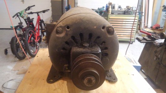
Front

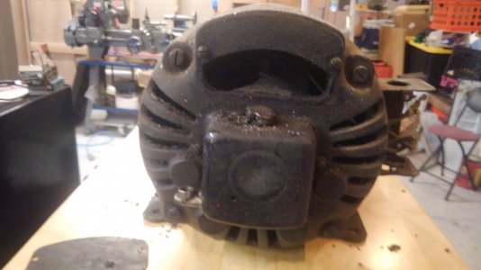
Back

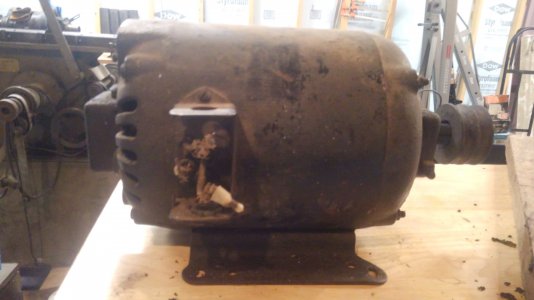
Side. Two wires are connected together, this shorts out the 110v coils and allows the 220v coils to operate. These pictures were before I cleaned a little and pulled the back of the motor off. The wires now actually have some insulation.

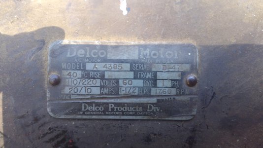
The tag.

Thanks for any help!
So, the motor turns over freely by hand. I did pull off the 'back end' (non-output shaft end) to vaccuum out a little bit of gunk and to look at the wires and brushes (they look fine actually). I also checked the wires going through the case and did ohm out the wires to make sure I don't have any obvious shorts.
My question is how would I wire up the motor to test it? The 220v outlet I have avalible is the 4-prong style used for a dryer. I have 4 wires - red, green, white and black. I know that green is ground (I know this is temporary, but I still want to have the motor grounded!), white is neutral, but what do I do with the red and black. How do I get from the 3 wires (red, black and white) to the 2 on the motor? The motor leads have no differeing colors that I was able to see (I did check).
I also have a simple toggle switch (from ACE) that is intended for machinery motors rated at 100-240v and up to 30 amps. I don't intend to keep this switch for the motor, I simply want something a little easier/faster/safer (?) than yanking the plug out if I have smoke.
I suppose a few pictures are in order.
Front

Back

Side. Two wires are connected together, this shorts out the 110v coils and allows the 220v coils to operate. These pictures were before I cleaned a little and pulled the back of the motor off. The wires now actually have some insulation.

The tag.

Thanks for any help!

