Restoration of BMW R69s engine

Can we get back to the R69S? lol
I have a smaller cousin, the R26, and have done a lot of work on both singles and twins of the era, working at a BMW bike workshop and dealer in the 70s in Germany and then in Melbourne, Australia. Rebuilt a few R69S in that time. Loved them! Lots of torque for the size, 42Hp was a lot in the 60s - not so much now.... but these engines would run at max power for hours and hours continuously. I one did a 1000km non-stop trip Cologne - Vienna and again non-stop back a few days later on an R50S - never missed a beat and sat on the redline pretty well all the way on the Autobahn. Pretty crazy thing to do, but then I was 18..... now I'm 70.....

Hi Joe

The 69s engine rebuild project is grinding on slowly. Here is what the current status is.
1. The reproduction crankshaft I purchased from a supplier in Europe is proving to be a bit of a challenge.
I measured the alignment, the runout and the slide clearance on the big ends. The alignment was
+/- .625mm permissable misalignment +/- .2mm - well I adjusted the alignment down to less than .01mm
Well that seemed promising but now my runout is .05mm on the front shaft which holds the generator.
Permissable max runout is .02
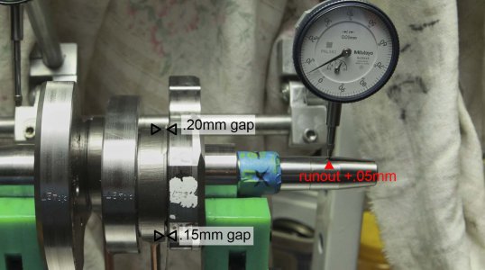
MAL_1076.jpg
So I am looking at this situation with a patient mind. The side clearance on the conrod to crankweb should be max .07mm.
Which is what the rear conrod is set at. It seems at a cursory glance that if I press the front journal/crankpin further onto the central web to make the clearance both .07mm then the runout will quite possibly be even worse.
So at the moment I am thinking before I rush in.

2. The second task to undertake is resizing the bores for the cam followers to take the oversized cam followers I have.
I initially thought I would ream the bores using an adjustable reamer. I have never done reaming before so I turned up some brass bushes to match the undersized spec of the bores and reamed them out to fit the new cam followers.
I was not happy with the result. Too much chattering resulted in a sort of corrugated surface inside the bores.
So I investigated a spiral reamer, but it would have to me custom made and the quoted price was $300.
The other consideration was even with the custom reamer I was advised that the surface finish would be inferior to honing.
P180 hoane.jpg
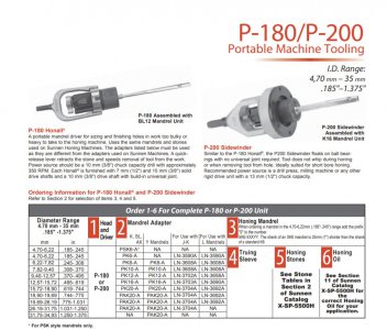
Enter the P180. I went and met with the suppliers and looked at the price of the P180. Expensive at about $1200 for the complete tool to do the job.
So what I have done is I have just purchased the mandrel and grinding stones and grinding oil.
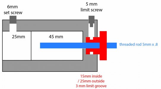
The current project to make up a tool which is basically a custom universal joint with a threaded adjuster to expand the mandrel to the exact dimension.
sunnen no 1.jpg
So here is the first part to be made. Which is sitting in the lathe awaiting my attention.

So there is the update on the R69s engine.
All comments and suggestions are welcome.
I am not a fitter and turner by trade just someone who likes to have a go and doing it as much as possible in my home workshop.


Mal
Toowoomba
Queensland
 
Bit more work on the adaptation of the P180 mandrel.
Still have to make the yoke.
Some of what you see is mock up to assist me to visualise the next step.

MAL_1108.jpg

View of the other side showing the cutaways to secure the slide pin.
MAL_1109.jpg

Here is the part assembled, still missing the drive yoke.

MAL_1107.jpg


Mal
 
Well today I used the hone tool to sort out the cam followers. The tool worked fine, though it is not idiot proof and care and sensitivity was still required to get a good end job.
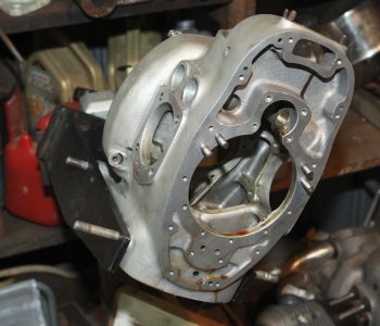
I fixed the crankcase in a comfortable position on the engine stand.
MAL_1119.jpg

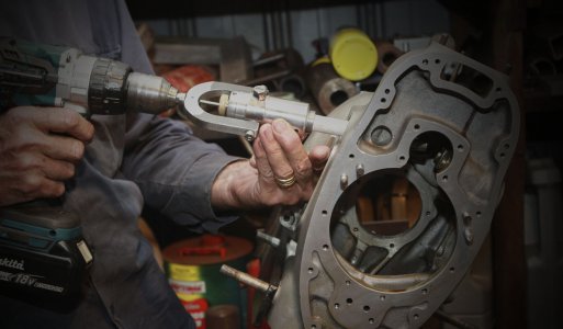
I then did about three operations to get to size. Measuring each time I withdrew the hone.
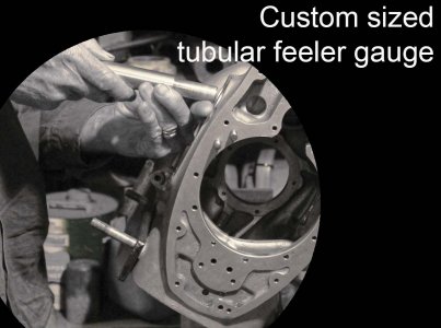
MAL_1132.jpg

I had turned up a tubular feeler gauge, instead of trying to use the new cam followers.
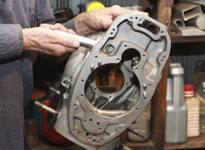
When the bore was to size I then tested the actual cam follower. Each one now has a designated bore to fit into.

MAL_1133.jpg

When the fit was satisfactory I was able to move on to the next bore.
MAL_1136.jpg

Thanks for taking the time to check out my project. I hope it helps you with something you are doing in your workshop.

Mal
 
OK, back to those crankshaft blues..... now there is a sad song in the making.

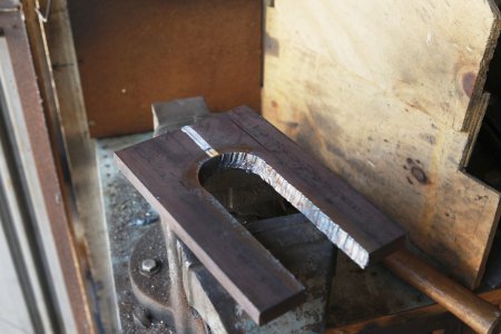
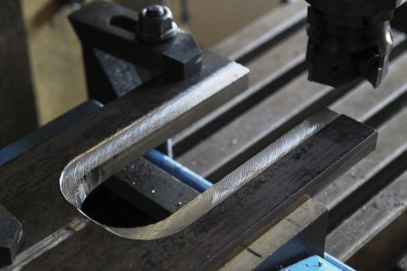
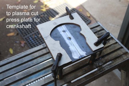
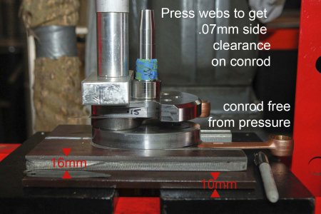
The next problem was there was too much side clearance on the front conrod. To press the webs closer together I needed some way of holding the crank in the hydraulic press.
So here are some pics of what I have been up too.

Mal
MAL_1142.jpgMAL_1145.jpgMAL_1146 1.jpgMAL_1147.jpg
 
I have always felt a bit cheated when I read about the old crankshafts and the response is, "if these needs repair take it to an expert."
Then when you get something from an expert re the crankshaft, the line seems to be generally, well in simple terms the crank is pushed together carefully and it can be difficult and I won't go into the detail here.

Well I found a clip on youtube from a guy who posts under 2stroke stuffing. He has a very informative video on the process for a single cylinder crank.

So I got to reflecting on the previous lack of detail on assembling crankshafts and I now have two options.
1. It is difficult to explain, and yes I do it but I really don't know how to actually explain what I do, but it works (well I can understand now why it is hard to explain - not impossible of course but difficult yes)
2. Maybe for some they assume that if they tell people there secrets, everyone including the dog will be assembling crankshafts and they will be out of business.

Well my comment on the second perspective is; anyone who is going to do it, will do it and learn how anyway and also explaining how it is done is easy compared to the perseverance required to get the job done.
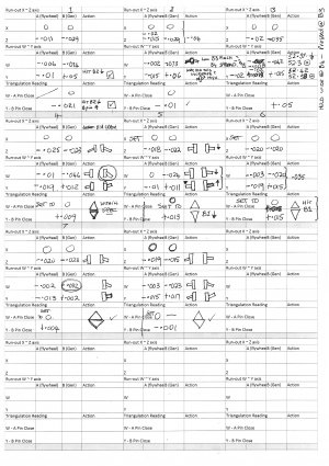
Here is my chart I developed to help me track the incremental steps in just tweaking an assembled crank. I have no cookbook for the complete job, but it would have to have several pages.

I really have to thank 2stroke stuffing for the guidance, it has made a lot of difference to the process.
Well not finished yet but nudging my way towards completion.

Mal

EPSON009.JPG
 
What a pain! I thought this was a new crank set. And if so that it should be ready to go. Well at least you have the equipment to deal with it. And the machine tools to make what you need. I never had a lathe or mill to make what I needed I just had to bodge something together and try to get a precision result. Thinking back the only shop I worked in that had a real press was in college.
 
Back
Top