Restoring (hopefully) my new Smart and Brown SAB

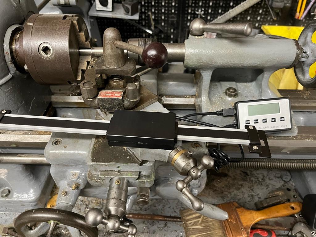
If you are adjusting the TS close to the spindle, you need to keep in mind that that is where the wear is probably the greatest. As you move the TS away, it might be moving off center, probably higher and maybe even side to side. I'd turn a piece of stock over 4" ( large enough diameter to not need support ) and compare that to your readings of the longer supported piece over the same 4". That should show you if the TS is influencing the cut. I also find it helpful to measure diameter every inch to see if the difference is cone shaped or has a belly. Also make sure there isn't runout on the live center or that you can influence it by pressing your finger against the stock at that point. A poor live center can screw up your measurements near the TS.

My 1024 has a heavy bed and wide ways but they do show enough wear that I expect even the S and B hardened ways are not terribly hard so some wear is to be expected, especially if the apron and carriage oiler isn't working well or is poorly designed. I don't think the 1024 oiler system is the best in that area and that creates wear. My 1024 shows enough wear i can feel it with my finger but still turns to about .001. My CVA has less wear and turns to within a couple tenths over a 6" distance.

Dave
 
My motivation and energy has been lacking when it comes to finishing off the lathe lately, so I’m going to post some ‘part way through’ pictures here to hopefully spur me on.

Firstly, the X axis scale arrived (it took a long time from china) today:

7fe8ffb8f3680e95d5acdc6888257025.jpg


Getting this fitted will complete all of my mill and lathe DRO axis.

This pic is from my mill but shows the touchDRO setup on the tablet. The tablet will swivel to the right which is where the lathe is. Handy to be able to mount the tablet once and use for both machines.

bab079e8565501ca9712511373d29674.jpg


The other part finished project is the ELS conversion:

d48cd59f08b6724e2bcc6522461d37f3.jpg


I’d say its half completed on the bench. This needs finishing and then mounting. The stupid thing is, the reason I stopped is that I can’t find a electrical enclosure big enough to fit everything. I must be being dumb, but I just can’t find one. Others I’ve seen/read have made their own. I don’t want to go that route.

Right. Hopefully posting my shameful lethargy to you lot will spur me on to get this thing ‘done’


Sent from my iPhone using Tapatalk
 
For my G0704, I just got an old computer case. Stripped the inside and used that for installing all parts… Worked well and cost me nothing…

86457371-DD2D-45F7-AC0C-5403EA480F68.jpeg
6A970375-7A8D-47C3-AA12-A1141F541299.jpeg
D12F6463-319B-45B6-B878-56984E9DFE65.jpeg
 
Last edited:
For my G0704, I just got an old computer case. Stripped the inside and used that for installing all parts… Worked well and cost me nothing…

Yeah, this is the only thing I can think of.


Sent from my iPhone using Tapatalk
 
That’s a neat looking setup. It’s worrying me that you’ve a lot more components and wires than me! Is this all Just for your ELS? Is it the clough42 one?


Sent from my iPhone using Tapatalk
Apologies for the confusion... I was just giving you the idea of finding an old computer case and using that.

This was the setup I used to convert to CNC my G0704 milling machine... more parts required...

 
Apologies for the confusion... I was just giving you the idea of finding an old computer case and using that.

This was the setup I used to convert to CNC my G0704 milling machine... more parts required...


Ah, i see. That’d explain all of the extra stuff.


Sent from my iPhone using Tapatalk
 
Posting my laziness this morning has helped. I got some time to continue to work on the electronics. The wiring is mostly done:

91b9651447528e94025b182fcad8662b.jpg


My lack of knowledge on steppes and controllers is showing through though. In the Clough42 diagram, it shows that there should be a FLT+ and FLT- on the controller that wires to the circuit board:

b1015bc082f396bb9d8303b7c320bfda.jpg


I understand these are Fault signals.

I have the following:

f302634ef1443734326fa643708d49f5.jpg


Sent from my iPhone using Tapatalk
 
ALM = ALARM, I think is the same as fault. The docs on this stepper motor driver are confusing. I also have the CL57T. If it followed normal convention, the COM would be connected to ground, and ALM would be pulled up to +3.3V or +5V depending on what your micro-controller needed. I have made my own ELS using a different processor. At the moment, I don't use ALM. However, I am running the wires to my control box, to (eventually) detect the signal. The docs on the CL57T ALM signal make no sense to me - the schematic seems to have multiple errors and is not consistent with the text. When I cable everything up, I will test it and figure out how to use it. I have my power supply and CL57T in one box, and my processor and display will be in a much smaller box on the headstock. I am using a touch screen for the user interface. My processor PCB is about 100 x 100 mm and includes a display.

I think, if you check the Clough42 code base, that the Fault signal is not used, but please confirm that for yourself.

Thank you. I had wondered if alarm was similar to fault. Theres only one ALM connection but two FLT (plus and minus), so how would they connect up?


Sent from my iPhone using Tapatalk
 
Back
Top