Reversing a single phase 120 V motor

Agreed. Look around the house, and shop. Very few 120V items use relays. almost all have the 120V right behind the switch. Electronic items are the main things I see looking around, taht do not, and they are likely done more for noise isolation, and simplicity in manufacturing, then to move the 120V away from the switch.
 
Agreed. Look around the house, and shop. Very few 120V items use relays. almost all have the 120V right behind the switch. Electronic items are the main things I see looking around, taht do not, and they are likely done more for noise isolation, and simplicity in manufacturing, then to move the 120V away from the switch.

Agreed-- I think it is more often than not--simply done for economics there within the manufacturing process. Saving that green. That and the electrical noise issue.

When looking at it from a global perspective, where the vast majority of the electrical component manufacturers are located, our 120V is already seen as a low voltage. On the other side of the pond anyway. Almost 80% of the world utilizes 230 volts for their common, everyday lighting and general purpose receptacles..even within their little huts. We're the only ones really using 120 volts.
 
Erich, do you have a three phase motor in your arrangement or did you just break your start winding's leads across contacts 2,3 and your nuetral across 1 for a single phase arrangement? Those are nice switches by the way...made fairly decent.
 
Erich, do you have a three phase motor in your arrangement or did you just break your start winding's leads across contacts 2,3 and your nuetral across 1 for a single phase arrangement? Those are nice switches by the way...made fairly decent.
I'd only had a single phase motor with that drum switch. Typically the 'reverse these two wires to reverse rotation' for single phase is how it works, so you just wire up the motor like normal, then have the two reverse-wires go through the two diagonal parts of that switch.

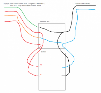
I wired the ground directly to the motor. I wired the lines to the unchanged wires directly. Then, I pulled the "red" wires (the ones needing switching) into the switch on 1 side, and the two line-ins into this switch as well.
 
297364

Here is how I wired mine. The motor side was slightly more complicated (additional wires/stuff since it was a dual voltage motor). I chose blue for Line in, since white shows up poorly :) There is also a ground that just goes 1 to the other.
 
I'm familiar with wiring, I had initially asked because we have a lot of outside readers that land on this forum and therefore desire some clarity. I knew you had a slightly unique situation, in that, it's not as simple as switching the two leads supplying the motor. After your pictorial, indeed you do. Essentially what someone did- either you, the manufacture or someone owning the setup before you, had the start winding leads extracted from inside the motor housing and pulled outside of it...this is not the case for most single phase motors. Others would have to dig those wires out from underneath the end cap and extend them to create a situation like yours. In your scenario, after that was obviously done, then that switch works great--we were just flipping the start winding leads.
 
Back
Top