Here is my latest mod to my Grizzly G1006 / RF-30 clone mill. Like everyone, I was annoyed by having to plan ahead so much in setting the head height so I could complete all the operations I had planned within the available travel of the quill. I searched online and YT many times for ideas and none of them really grabbed me until I saw the one that I based my design on. I was struck immediately that it was the one I wanted to use! As you'll see in the photos, it is a wishbone-type arrangement with the pivot about 16" away from the column and that really minimizes any errors due to play compared to a guide that is close to the column that even has its errors multiplied if it is closer to the column than the quill is.
After seeing the concept, I engineered it my usual way: seat of the pants and totally in my head. I admit there were changes and errors fixed as I went along and it began to take shape but I am quite happy with the end result and I don't particularly wish I had done anything differently.
I began with the idea of the clamp to go around the bottom of the column. I got to use my lathe and my mill, yay! I ordered a disk of aluminum on eBay from a guy who offers many diameters and thicknesses for quite reasonable prices. I bought one 6" diameter, 1" thick (came 1.050" so I could face it off no problem). I faced both sides and made it exactly 1" thick, though that wasn't important.
View attachment 324631
Next I scribed 2 lines across the center perpendicular to each other. Then I added two more lines each 10 degrees offset from one line towards what would be the back. This was because as I mocked things up that looked about right to keep the balls in the Heim joints basically in the center of their sockets. A word of warning: don't be like me and cheap out on the Heim joints. I bought economy ones on eBay that didn't have Teflon inserts in them, just the ball and the steel shell. I asked the seller before I ordered about whether his joints had any discernable play in them. He didn't really say, and they did. I cobbled together some parts to squeeze the shell of the joints using my press into closer contact with the ball and was able to actually put some preload on the balls, so zero play now. I ordered some right-hand and some left-hand threaded joints as at that point I was envisioning adjustable tie rods in some way but in the end that wouldn't have worked so all RH would have been fine.
Next the disk went back in the lathe to have a center hole bored out. I chose to start with a 3.5" hole saw so I wouldn't have to spend a long time boring but once the teeth were out of view I had to back it out over and over and over to clear the packed aluminum from the teeth! Finally made it through and then it was simple to bore it to the diameter of my column. I see machines later than mine have a 4.5" column? Mine measured 4.016", probably 100mm.
View attachment 324632
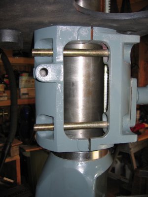
Now the ring went into the milling vise with the future cut line (without the 10 degree offsets) as nearly horizontal as I could manage. I located one edge and one side of the ring and then used an end-cutting .750" end mill to make the recesses for the 1/2-20 socket head bolts I would use, centered over the future cut surfaces. I could pretty much only go deep enough to get a full-round spot for the same reason I am making this, the head was too high after allowing for the drill chuck and bits I would use for the bolt holes. I drilled all the way through with a tap drill and then to the cut line with a clearance bit.
View attachment 324635
I would have liked to then saw off the top half with a cutter so that I could keep things square but I didn't have one (I do, but no arbor as yet). I took the ring to the band saw and cut it in half. I mounted each half in the vise and faced off the rough ends. Then I put the half that needed to be threaded back in the vise, again as level as I could and then tapped the holes with a spiral machine tap under power, no danger because they were through holes. My mill with its stock 4 pulleys can go down to 85 RPM. I had to back the tap out manually, that's why I'm going to add a reversing switch. It will be easy and will be my next mod and post.
Next I put one half in the vise with a 10 degree mark vertical and did a spot face, then drilled and tapped for the bolts for the Heim joints.
View attachment 324636
Lastly, I put the left half in the vise and milled a slot for the height adjusting rack to go through, aligned with the 90 degree line I scribed. Here is the finished ring.
View attachment 324637
View attachment 324639
Now it was time to think about the next stage. For the tie rods I used 1/2" black pipe and turned threaded inserts to weld into them. I made the pipes about 14" long because it looked right and I didn't want to move my mill any farther from the wall. The pipes form a 20 degree V to go along with the two 10 degree offsets for the joint attaching bolts. I welded them to a stout piece of angle iron using my TIG welder which I am still terrible at but improving slightly.
As I scratched my head over how to attach the upper tie rods to the head, here is a place where my design diverged from the sketches I saw online. I had already added the 1" thick ring to lose vertical travel and if I attached the upper ties rods to the underside of the head I stood to lose more travel (plus how was I going to attach them, anyway?) I got the idea at this point to make the upper arm assembly wider so as to straddle the lower assembly as seen here:
View attachment 324640
View attachment 324641
View attachment 324642
By adding mounting brackets to the sides of the head I can lower it until the rods are all in the same plane. I twisted the brackets to the same 10 degree angle and tried my best to position the brackets so that the bolts are centered with each other. I enlarged the mounting holes a little on the left bracket to allow moving it up or down a little to hopefully eliminate any left or right angular motion at the end of the rods as they pivot up and down. Here it is fully installed:
View attachment 324643
View attachment 324644
View attachment 324645
Next, I had to try to align everything as good as I could. I had to think a while about how to square up the lower collar and what I ended up doing was to use a framing square (a woodworking tool, I'm sorry!) to go from the shell of the Heim joint down and over to the edge of the table on both sides and shift the collar around the column until the measurements matched. I put a piece of very true .750" round stock in a collet and placed a dial indicator against it and then cranked the head up and down. I was getting some drift so I moved the left upper bracket up or down a little until it seemed to be eliminated. After putting the preload on all the joints, the indicator wiggles a little when you are cranking but there is no actual play and it always returns to zero. That is, after I discovered that the indicator would shift 5 to 8 thousandths when I would tighten the head clamping nuts. I experimented by tightening each nut individually and then turning the crank down a little, then I would carefully loosen the nut just until the head dropped. I put an arrow straight up on each nut right at that point and I actually find that the difference between the head being free to move and the nuts being tight to clamp the column is only about a quarter turn! This will help me by not having to needlessly turn the nuts until they are free of all tension as I was before, and by having them close to clamping down, there is now no movement of the indicator when I tighten or loosen them.
View attachment 324646
I had some nagging doubts about how well this was going to work but I am very pleasantly surprised. When moving the head up or down almost 5 inches (the length of my measuring round stock) there is virtually no change at all! I pronounce it a success that I will really enjoy. I hope it helps someone else with their design sometime.
Rob