- Joined
- Oct 31, 2016
- Messages
- 2,643
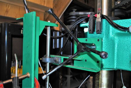
I use a dial indicator combined with a stop to bring the head back to position. Put the stop and DI against the spindle and zero the DI. Move the head wherever you need to and then bring it back until the DI reads zero again as the spindle touches the stop. Works for me.