RF-30 late nineties mill drill spindle runout vs quill runout

dansawyer

Registered
Registered
Joined
Jun 13, 2018
Messages
442
The machine is a late nineties RF 30 in generally in good shape albeit a bit dirty.
Spindle measurements I believe good. When the quill is locked and a ground center placed in the spindle and measured the dial indicator shows about 4 tenths total run out. This is consistent for push and pull on the spindle and when the spindle is rotated.
Quill measurements are another matter. When the quill is unlocked the run out is about 4 thousands. When the quill is locked there is no measurable run out.
Is there a an adjustment for quill run out? Are there quill specific bearings?
I have not found quill specific maintenance.
 
There are no bearings for the quill itself. The quill runs inside the bare head casting. There is a screw and nut between the quill locking handle and the spring housing that allows you to take up side-to-side play between the spindle and head casting but beyond that, nothing. Most of the time you will lock the quill before taking a milling cut so this set up works okay. Aside from keeping the outer surface of the quill oiled, no maintenance is needed for the quill itself.

As for run out, it isn't clear to me how you are measuring it. Can you post a pic of your set up?

Just to be clear, the measurement that matters is the concentricity of the spindle inside the quill. This is a measurement of the accuracy of the spindle and that measurement is a compound measurement that includes the influence of the spindle bearings and the drive sleeve bearings. What makes life difficult for RF owners is figuring out how much of the measured run out is due to the drive sleeve and how much is due to the spindle bearings. The only way to truly separate the two is to remove the quill from the head, put it v-blocks and measure the run out of the spindle; this tells you how good the spindle bearings really are. If you get anywhere under 0.0002" TIR when measured this way then the spindle bearings are probably okay and simply need to be cleaned, re-greased and have the preload adjusted. It also tells you that your spindle is pretty straight and can be used as is provided the spindle taper is okay. If it is more than about 0.0002" TIR then you need to check preload to be sure that isn't causing excessive run out. If preload does not handle it then the bearings are suspect.

EDIT: It came to me at 2am while I was trying to fall asleep that another way to separate the influence of the drive sleeve from the spindle is to physically remove it. That is, you can just pop the drive pulley off and remove the drive sleeve out the top. This leaves the spindle free of any other influence and you can assess spindle run out in the quill bearings accurately, without the need for v-blocks. Then you can replace the drive sleeve and see how that impacts run out.

Once you know the spindle bearings are okay then the quill can be reinstalled in the head and whatever run out beyond what you got in the v-blocks will be due to the drive sleeve bearings. The drive sleeve bearings support the drive sleeve, which is what transfers the rotational power from the front pulley to the spindle. The drive sleeve has teeth in the inside that mesh with the teeth on the upper spindle and that is how power is transferred. If the drive sleeve bearings are bad then the drive sleeve will move around and the upper spindle will oscillate; this definitely affects the accuracy of the spindle, despite the fact that the spindle runs in separate bearings.

If you simply wish to know how accurate the overall spindle/drive sleeve assembly is then you have to measure static concentricity of the spindle taper itself. (Even more accurate is a dynamic tester for concentricity but those cost big bucks and are not found in the typical hobby shop.) Using a chuck or collet to hold a pin and then measuring the pin adds too many interfaces and tells you nothing of real value due to all the stacking tolerances.

To do this properly, you need a tenths-reading dial test indicator so you can put the tip of that indicator up inside the spindle taper; you cannot use a dial indicator for this unless it has an attachment that allows for this function. You also need a very rigid indicator stand like the old 2-arm stands to hold that indicator; the popular Noga-style articulating arm stands work but are really not that rigid.

Assuming you have the proper equipment, lock the quill. Clean the spindle taper really well and then bring the indicator needle into contact with the spindle taper about 1/3 of the way in. Preload the indicator by about 0.015" or so, then zero the dial. Put a piece of masking tape on the non-moving part of the quill and use a Sharpie to mark both the outside of the quill and the tape; these marks allow you to accurately turn the spindle and then bring it back to its origin. With the DTI at zero, turn the pulley at the top (disengage power and the belts) by hand and make one complete revolution and realign your Sharpie marks. The DTI should return precisely to zero. If it does, this tells you that your set up is repeatable and can be relied upon to assess run out. Then make one more revolution, this time watching the needle for maximum deviation. Make another Sharpie mark on the spindle to tell you where that deviation is and write down the magnitude of the deviation, then return to your origin. If you are again at zero, go back to that deviation mark and make sure it replicates; if it does then that is the static run out of your spindle. Repeat this procedure with the DTI needle at the halfway mark and at 2/3 of the way into the spindle taper. If it all repeats the same then this tells you how much the spindle run out is and it also tells you how accurate the spindle taper itself is.

To be very clear, this is done manually without power. Doing a run out check under power tells you almost nothing. The same procedure is done with the quill up on blocks, by the way.

Hope this helps.
 
Last edited:
Thank you for the detailed reply. It has taken me a while to get back to this and to absorb enough to figure out how to proceed. Attached are two photos, the first is the setup to measure the quill and the second to measure the spindle.
As I said the quill has quite a bit of what I will call run out when it is not locked and almost none when it is locked. That said all I have is a .001 reading DTI. I am in the process of purchasing a tenth reading DTI. On of the steps in the project is to drill precision diameter holes to hold bearings. I am concerned that quill run out will cause the holes to be enlarged. I will test this on scrap material first.
The spindle measurement shows between 3 tenths and 5 tenths estimated on the .001 reading indicator. This is taken on the outside of the spindle and as you pointed out that may not reflect the inside concentricity. The next step in this process is to acquire a tenth reading DTI and take the inside measurement.
This raises a couple of questions:
1. If the quill is locked is there any effect from the pulley spindle drive mechanism that can affect spindle run out?
2. With the quill locked if I read your note correctly the TIR on the inside of the spindle should be less than .0002.
3. If the TIR reading is within tolerance can the spindle bearings be regressed without removing the quill? I read one post that indicated the spindle could be removed from the top by removing the pulley and the upper nut holding the spindle thrust bearing in place. Is this easier than removing the quill? Is there an advantage to removing the quill first?
4. Are there bearings / surfaces in the spindle drive mechanism that require removal to be lubricated?
Thanks again for the post. It will take a couple of weeks from here to work through all of this.

quill.jpg


spindle.jpg
 

Attachments

  • spindle.jpg
    spindle.jpg
    29.5 KB · Views: 103
The pics help, Dan.

As I said the quill has quite a bit of what I will call run out when it is not locked and almost none when it is locked. That said all I have is a .001 reading DTI. I am in the process of purchasing a tenth reading DTI. On of the steps in the project is to drill precision diameter holes to hold bearings. I am concerned that quill run out will cause the holes to be enlarged. I will test this on scrap material first.

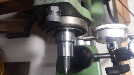
First, some basics. You are using a Dial Indicator (DI); some call it a Drop Indicator. It is useful for many things but for measuring run out on a spindle, you need a Dial Test Indicator (DTI). The needle of a DTI attaches to the body of the indicator via a hinge; this is the type you need for this sort of work and ideally, you want a tenths reading indicator (0.0001") with a decent range. I will send you a link to a good one by PM. A tenths reading DTI is too sensitive for general work, like aligning a milling vise or a part, but it is exactly what you need for assessing spindle concentricity like you're doing here. For general work, a 0.0005" DTI is more useful.

Regardless of how accurate the spindle is, drilling holes with a drill is not a precision process and probably not precise enough for bearing fits. For that, you need to bore the hole with a boring head and use some skill in doing it. Not to worry; that skill will come and you can ask the guys about boring heads. You are right though, in that excessive run out will affect the accuracy of whatever you mount in the spindle so an accurate spindle is important.

How accurate is the real question. There are no standards for Asian mills to my knowledge. My personal RF-31 spindle runs out at just under 0.0001"TIR but I think that anything under 0.0002"TIR would be pretty good. This run out stuff matters because it affects accuracy, tool life and finishes, and this applies to anything you put in the spindle. In my opinion, it is a good idea to get run out as low as you reasonably can. Unfortunately, I do not know how good you can get run out with properly preloaded stock tapered roller bearings.

As for measuring the run out of the quill, that matters only in that you want to assure the quill runs accurately in the head stock casting. You cannot adjust it but if it is really bad then you cannot fix it and you may as well scrap the mill. Yours sounds like it is fine. You can further evaluate it by pulling the quill out of the head and looking at it (and the inside of the head) for rub marks. If there is no excessive wear then the quill is probably just fine. Taiwanese mills are usually pretty accurately machined in this area so I expect yours will be okay ... fingers crossed.

This raises a couple of questions:
1. If the quill is locked is there any effect from the pulley spindle drive mechanism that can affect spindle run out?
2. With the quill locked if I read your note correctly the TIR on the inside of the spindle should be less than .0002.
3. If the TIR reading is within tolerance can the spindle bearings be regressed without removing the quill? I read one post that indicated the spindle could be removed from the top by removing the pulley and the upper nut holding the spindle thrust bearing in place. Is this easier than removing the quill? Is there an advantage to removing the quill first?
4. Are there bearings / surfaces in the spindle drive mechanism that require removal to be lubricated?
Thanks again for the post. It will take a couple of weeks from here to work through all of this.

1. Absolutely. The spindle runs in two bearings inside the quill; these are the spindle bearings. The top of the spindle is driven by the drive sleeve; the drive sleeve runs in a separate pair of bearings. The front pulley is pressed onto the drive sleeve and this is what transmits power from the motor. So, the motor drives the pulley, the pulley turns the drive sleeve, the drive sleeve turns the spindle and the spindle turns. You can imagine that if there is excessive play in either the drive sleeve bearings or the spindle bearings, run out will increase. This is not theoretical. I wrote up exploring this chain in the Rong Fu section of the forum; check it out.

2. 0.0002"TIR should be acceptable for hobby shop use, I think. You have to keep in mind that spindle run out is one thing but everything you run in that spindle will have its own run out - chucks, end mills, everything. Spindle run out magnifies the run out of everything else you put in the spindle and this is why we are seeking ridiculous amounts of precision in the spindle; we need to minimize the run out of the tools we use. For example, we know that for every 0.0001" of spindle run out, we reduce end mill life by 10%. If your spindle has 0.0003"TIR you are looking at a theoretical 30% reduction in the life of that end mill. This also affects the accuracy of the tool and the finish it can produce. In my point of view, it is wiser to spend the money to get the spindle accurate because this will save you money on every single tool you put in that spindle.

3. I think you are asking about how to access the spindle bearings for maintenance? If so, then here is the answer. No, in order to service the spindle bearings you must drop the quill out of the machine and press the spindle out of the quill. The upper spindle bearing will lift right out of the top of the quill once the spindle is out. The lower bearing can remain in place on the spindle. Then you can clean each bearing completely, re-pack it with grease, reinstall the spindle and adjust preload. This procedure is supposed to be done annually if the machine sees regular use but you can probably go a bit longer in a hobby shop. I don't want to bother with this that often, which is why I used sealed bearings that require no maintenance until they need changing.

Likewise, the drive sleeve bearings must be removed and serviced. No preload is used on these bearings but they do need to be cleaned and re-packed with grease periodically. Or you can just swap them out for sealed deep groove bearings and not have to maintain them at all.

I know this all sounds like a lot of work and it sort of is. However, if your spindle is otherwise in good shape but the bearings are junk then the spindle will not remain in good shape. That spindle is not hardened and the pounding it takes when bearings are not good will eventually wear that spindle taper; I had to replace my spindle because of this so believe me, this is true. My suggestion to you is to evaluate the spindle properly and if it is found to be out of spec, with maybe greater than 0.0002"TIR, then commit to replacing the spindle and drive sleeve bearings. I would highly recommend you use precision spindle bearings and if I were you, I would use sealed angular contact bearings instead of open tapered roller bearings that require periodic maintenance. I would use sealed deep groove ball bearings in the drive sleeve instead of unsealed radial bearings; the sealed deep groove bearings will take higher axial and radial loads and require no maintenance for the life of the bearing.

I forgot to emphasize that you should check the spindle taper. Put the needle of the DTI inside the spindle taper and slowly turn the spindle by hand. Watch the needle as you do this; if it moves much at all then that taper is worn and the spindle needs to be replaced. Do this check at three levels - 1/3 in, 1/2 in and 2/3 of the way in - if there is no significant needle movement at all three levels then your taper is probably fine. If it swings then the taper is out of round and should be replaced. MSC should still stock the spindle, I hope.

It is worth evaluating and sorting out your machine. Do it, and it will serve you well for many years.
 
Last edited:
Back
Top