I'm running out of ideas to mod my Grizzly G1006! This may be the last one but I have really enjoyed putting my personal stamp on it, making everything just as I want it.
This is how I put a reversing switch on it, easy and pretty cheap. I decided I needed this after doing some power-tapping recently on my guide project. My machine can go as low as 85 RPM and the tapping went fine. They were through holes, otherwise I probably wouldn't have done it but I had to back out the tap by hand because no reverse!
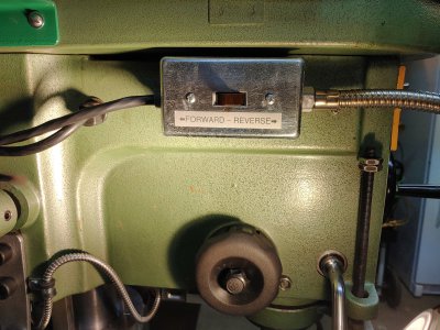
This mill didn't have a wiring diagram in the manual or in the box cover but some Googling seemed to confirm that the two black wires from the motor (#5 and #6 on my motor) were the reversing wires. Basically they just need to swap positions before powering up to change the running direction. I found a piece of 14 gauge 4-conductor wire (16 gauge would be fine, too). One of my wires is green but we don't need it for grounding purposes so it is available for us to use as a normal conductor. You could put some other color tape on it if you think someone might be confused by it someday when you are dead and gone. I mounted a small steel handy box on the left side of the head and ran the wire, attaching it to the existing power wire with a couple of cable ties. When you are drilling the holes to mount the box, take the front cover off of the head so you can see anything in the way that might get damaged by the drill. I got lucky, you might not.
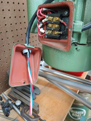
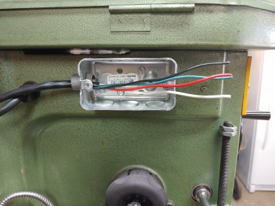
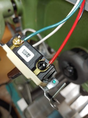
My motor reversing wires had U-shaped connectors on them and I found that they fit snugly into insulated female spade connectors as you see here:
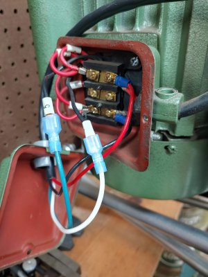
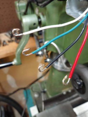
I connected my black and red wires to the black and red wire terminals coming from the power switch. There was room in the cover to make a hole to fit a snap-in wire clamp. I drilled the hole using a large step bit, the best way, I think, to make smooth holes in thin sheet metal. Then I was ready to tuck the wires into place and put the cover back on. The wire I used is plastic-jacketed, not rubber, and stranded though the strands are thick. Not really an issue as it barely has to flex when adjusting the belts. Since my wires are stranded, I tinned them with solder before bending to shape so they would hold their shape under the switch screws.
For my switch, I just used a regular household 4-way wall switch. In one position the input leads connect directly to the output leads, straight through. When toggled, the output leads cross over to the opposite input leads. I found a switch with a brown toggle on Amazon for half the price of other colors, so good enough. Connect the red and black wires to the input terminals and the other two wires to the output terminals, either way. Now you are ready to test it! Turn on the power switch and see if the direction the motor runs agrees with the direction of the toggle. If it isn't correct you don't have to swap any wires, just turn the switch end-for-end before mounting it. Now you can run your mill in reverse!
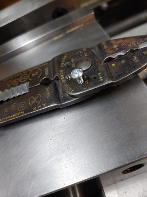
When putting in the screws to mount the switch I found that they were a little too long. Just in case you don't know what those threaded holes are for in your crimping pliers, they are for shortening screws. Put the screw in the appropriate hole (from the threaded side only) to the depth you choose and squeeze the handles. The screw with be sheared off and the crushed threads will be straightened as you remove what's left of the screw.
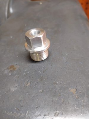
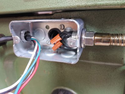
You may have noticed something else connected to the switch box in the previous photo. Once I had mounted the box, I remembered I had an old gooseneck work light and this looked like a great place to mount it. I disconnected the flex portion from its mounting base and found that it had a 1/8" straight pipe thread on the end. I made this piece to mount it to the box. One end is a 1/2" male straight pipe thread and the other, of course, is tapped for 1/8" pipe thread, tapped deeply enough for the gooseneck fitting to bottom out against it.
I have had my metal lathe for over 40 years but the biggest desire for a mill for me was the ability to machine perfect hexagonal shapes. It's just so cool, somehow! I recently bought square and hexagonal collet blocks and collets and this was the first use I had for them. I haven't had any past experience with collet chucks and I was considering getting 5C collets but then I read that ER-series collets have a much wider gripping range and that made up my mind. I went with a set of ER-40 collets and blocks and today I just ordered a ER-40 collet chuck for my lathe.
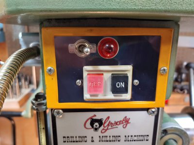
I took off my power switch plate and found just enough room to mount a toggle switch for the work light. I attached wires with eyelet connectors to the incoming power wire terminals. If you want to be proper about things, make sure you connect the switch to the hot lead (black in my case) and that you make sure that is the wire that leads to the center contact in your light socket. If you are wired for 220 volts then you might want to use a double handy box with room for a second switch and power cord for the lamp. It was difficult working with my mill's power switch as there was practically no slack at all in the wires, but I got it done. I used a 7/8" hole saw to make an opening in the head behind the center knockout of the box and pushed in a plastic bushing to protect the wires. Remember what I said about looking inside before you drill! I cable tied my lamp wires to the existing wires inside the head to make sure they stayed away from the quill. I bought a 100-watt-equivalent LED floodlight bulb and now there is plenty of light!
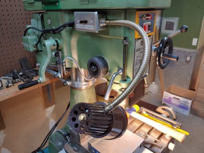
So, there you have it. I hope it inspires someone.
Rob
This is how I put a reversing switch on it, easy and pretty cheap. I decided I needed this after doing some power-tapping recently on my guide project. My machine can go as low as 85 RPM and the tapping went fine. They were through holes, otherwise I probably wouldn't have done it but I had to back out the tap by hand because no reverse!
This mill didn't have a wiring diagram in the manual or in the box cover but some Googling seemed to confirm that the two black wires from the motor (#5 and #6 on my motor) were the reversing wires. Basically they just need to swap positions before powering up to change the running direction. I found a piece of 14 gauge 4-conductor wire (16 gauge would be fine, too). One of my wires is green but we don't need it for grounding purposes so it is available for us to use as a normal conductor. You could put some other color tape on it if you think someone might be confused by it someday when you are dead and gone. I mounted a small steel handy box on the left side of the head and ran the wire, attaching it to the existing power wire with a couple of cable ties. When you are drilling the holes to mount the box, take the front cover off of the head so you can see anything in the way that might get damaged by the drill. I got lucky, you might not.


My motor reversing wires had U-shaped connectors on them and I found that they fit snugly into insulated female spade connectors as you see here:

I connected my black and red wires to the black and red wire terminals coming from the power switch. There was room in the cover to make a hole to fit a snap-in wire clamp. I drilled the hole using a large step bit, the best way, I think, to make smooth holes in thin sheet metal. Then I was ready to tuck the wires into place and put the cover back on. The wire I used is plastic-jacketed, not rubber, and stranded though the strands are thick. Not really an issue as it barely has to flex when adjusting the belts. Since my wires are stranded, I tinned them with solder before bending to shape so they would hold their shape under the switch screws.

For my switch, I just used a regular household 4-way wall switch. In one position the input leads connect directly to the output leads, straight through. When toggled, the output leads cross over to the opposite input leads. I found a switch with a brown toggle on Amazon for half the price of other colors, so good enough. Connect the red and black wires to the input terminals and the other two wires to the output terminals, either way. Now you are ready to test it! Turn on the power switch and see if the direction the motor runs agrees with the direction of the toggle. If it isn't correct you don't have to swap any wires, just turn the switch end-for-end before mounting it. Now you can run your mill in reverse!


When putting in the screws to mount the switch I found that they were a little too long. Just in case you don't know what those threaded holes are for in your crimping pliers, they are for shortening screws. Put the screw in the appropriate hole (from the threaded side only) to the depth you choose and squeeze the handles. The screw with be sheared off and the crushed threads will be straightened as you remove what's left of the screw.

You may have noticed something else connected to the switch box in the previous photo. Once I had mounted the box, I remembered I had an old gooseneck work light and this looked like a great place to mount it. I disconnected the flex portion from its mounting base and found that it had a 1/8" straight pipe thread on the end. I made this piece to mount it to the box. One end is a 1/2" male straight pipe thread and the other, of course, is tapped for 1/8" pipe thread, tapped deeply enough for the gooseneck fitting to bottom out against it.

I have had my metal lathe for over 40 years but the biggest desire for a mill for me was the ability to machine perfect hexagonal shapes. It's just so cool, somehow! I recently bought square and hexagonal collet blocks and collets and this was the first use I had for them. I haven't had any past experience with collet chucks and I was considering getting 5C collets but then I read that ER-series collets have a much wider gripping range and that made up my mind. I went with a set of ER-40 collets and blocks and today I just ordered a ER-40 collet chuck for my lathe.

I took off my power switch plate and found just enough room to mount a toggle switch for the work light. I attached wires with eyelet connectors to the incoming power wire terminals. If you want to be proper about things, make sure you connect the switch to the hot lead (black in my case) and that you make sure that is the wire that leads to the center contact in your light socket. If you are wired for 220 volts then you might want to use a double handy box with room for a second switch and power cord for the lamp. It was difficult working with my mill's power switch as there was practically no slack at all in the wires, but I got it done. I used a 7/8" hole saw to make an opening in the head behind the center knockout of the box and pushed in a plastic bushing to protect the wires. Remember what I said about looking inside before you drill! I cable tied my lamp wires to the existing wires inside the head to make sure they stayed away from the quill. I bought a 100-watt-equivalent LED floodlight bulb and now there is plenty of light!


So, there you have it. I hope it inspires someone.
Rob

