- Joined
- Dec 29, 2017
- Messages
- 60
Good afternoon all,
(Evening?)
Well, just over 7 years ago, I disassembled my Busy Bee B096 (RF-31) milling machine in my old house, and moved to my new house. The new 'shop' didn't have 220 power, so it really wasn't a priority for me to worry about getting it up and running, not to mention that the first 5 years in the house, I was still in the Navy and too busy with sailing and work to deal with home projects.
Fast forward to now, and I've stepping into a civilian job (still in the Reserves though, so still busy on a part-time basis!) and I've got a bit more time, and now I'm working on a few of my own projects.
My lathe (PM 1030) is running fairly well, and now it's time to get my mill up and running. First problem - 220 - solution - long-term, get 220V run out to the garage - but that's going to happen in a couple of months...summer-ish likely. Solution - short-term - I bought a 10Kw generator that will provide backup power for the house when we have outages (I'll get a generator panel installed when we get the electrician out to do the other power issues.) The generator will also provide me power for the mill to run.
Yippee!
And yes - I know, you can re-wire the RF-31 for 120 at 16A, but that's beyond what the garage can run right now...2Hp would...not work. I can't run the lathe and the shop heater at the same time...
Anyhow, so, let's look at the mill. It's been 7 years since it spun and cut metal, and that's the exciting part. I spun it on Friday for the first time in 7 years. And as I did so, I realized that I'd need to properly tram the mill - and get it shimmed and aligned to actually use it accurately. In my old house, I just assembled it, and use it...I never really worried (or knew) about how to tram a mill, I just cut, and my hobby work, well, it worked well enough. Now, I'm looking for that accuracy.
So.
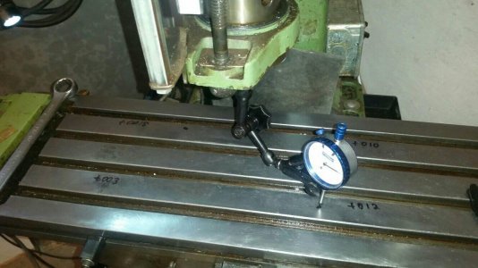
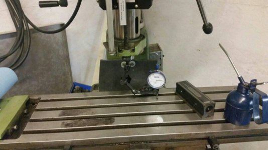
I dug out my Noga Tool - OMFG, I saw this mentioned on Abom's channel a while back on YT, and grabbed one for the lathe, and another for the mill, knowing I'd need it eventually. The Lathe one (fixed base) was night and day from the old cheap Chinese ones - WOW...very happy with the Nogas. Anyhow, stuck the Noga in a collet and did a sweep - ugh....first look showed it was mis-aligned by over 0.030" across an 8 inch span. Yikes.
So, I did some reading, did some Youtubing, and some cleaning - and this afternoon, I went out to have a more detailed look and try my hand at shimming things.
Lesson 1. Removing the drive belt from the spindle is a GOOD idea.
Lesson 2. When you get frustrated - walk away. A coffee is a good way to settle your mind when you're frustrated.
Lesson 3. Patience. Especially the first time around....
Lesson 4. Someone here had a thread from 2015 that had a document from 2009 that was enlightening - I was initially trying to level front/rear, then side/side. The document showed me that with a 4 bolt pattern, I should instead use corners - matching the bolt pattern.
I ended up also using a black marker on the surface to write down my measurements - again - things learned from the document.
So, my starting point showed me a 0.030" difference across 8 inches....that's far from good.
When I finished up with my shimming, I was -0.0015 on the top left, 0.0000 on the top right, -0.0010 on the bottom left, and +0.0010 on the bottom right.
So, that's between 0.0015" and 0.002" across 8 inches....which is still going to need some tuning, but for my first time, I'm pretty happy with it.
Now, the other thing I did in addition to cleaning the mill, was I took a stone to the top of the table - I realized that I'd inherited the mill (I got it used) with a lot of dents and bruises...now I realize how many and how big some are....so I took down some high spots, and it's looking a lot nicer now.
Yeah...looks vs function...well, now that the mill is somewhat aligned, it's time to go make some chips.
NS
(Evening?)
Well, just over 7 years ago, I disassembled my Busy Bee B096 (RF-31) milling machine in my old house, and moved to my new house. The new 'shop' didn't have 220 power, so it really wasn't a priority for me to worry about getting it up and running, not to mention that the first 5 years in the house, I was still in the Navy and too busy with sailing and work to deal with home projects.
Fast forward to now, and I've stepping into a civilian job (still in the Reserves though, so still busy on a part-time basis!) and I've got a bit more time, and now I'm working on a few of my own projects.
My lathe (PM 1030) is running fairly well, and now it's time to get my mill up and running. First problem - 220 - solution - long-term, get 220V run out to the garage - but that's going to happen in a couple of months...summer-ish likely. Solution - short-term - I bought a 10Kw generator that will provide backup power for the house when we have outages (I'll get a generator panel installed when we get the electrician out to do the other power issues.) The generator will also provide me power for the mill to run.
Yippee!
And yes - I know, you can re-wire the RF-31 for 120 at 16A, but that's beyond what the garage can run right now...2Hp would...not work. I can't run the lathe and the shop heater at the same time...
Anyhow, so, let's look at the mill. It's been 7 years since it spun and cut metal, and that's the exciting part. I spun it on Friday for the first time in 7 years. And as I did so, I realized that I'd need to properly tram the mill - and get it shimmed and aligned to actually use it accurately. In my old house, I just assembled it, and use it...I never really worried (or knew) about how to tram a mill, I just cut, and my hobby work, well, it worked well enough. Now, I'm looking for that accuracy.
So.
I dug out my Noga Tool - OMFG, I saw this mentioned on Abom's channel a while back on YT, and grabbed one for the lathe, and another for the mill, knowing I'd need it eventually. The Lathe one (fixed base) was night and day from the old cheap Chinese ones - WOW...very happy with the Nogas. Anyhow, stuck the Noga in a collet and did a sweep - ugh....first look showed it was mis-aligned by over 0.030" across an 8 inch span. Yikes.
So, I did some reading, did some Youtubing, and some cleaning - and this afternoon, I went out to have a more detailed look and try my hand at shimming things.
Lesson 1. Removing the drive belt from the spindle is a GOOD idea.
Lesson 2. When you get frustrated - walk away. A coffee is a good way to settle your mind when you're frustrated.
Lesson 3. Patience. Especially the first time around....
Lesson 4. Someone here had a thread from 2015 that had a document from 2009 that was enlightening - I was initially trying to level front/rear, then side/side. The document showed me that with a 4 bolt pattern, I should instead use corners - matching the bolt pattern.
I ended up also using a black marker on the surface to write down my measurements - again - things learned from the document.
So, my starting point showed me a 0.030" difference across 8 inches....that's far from good.
When I finished up with my shimming, I was -0.0015 on the top left, 0.0000 on the top right, -0.0010 on the bottom left, and +0.0010 on the bottom right.
So, that's between 0.0015" and 0.002" across 8 inches....which is still going to need some tuning, but for my first time, I'm pretty happy with it.
Now, the other thing I did in addition to cleaning the mill, was I took a stone to the top of the table - I realized that I'd inherited the mill (I got it used) with a lot of dents and bruises...now I realize how many and how big some are....so I took down some high spots, and it's looking a lot nicer now.
Yeah...looks vs function...well, now that the mill is somewhat aligned, it's time to go make some chips.
NS